IDENTIFICATION
OF
MAIN COMPONENTS I SYMBOLS
1. IDENTIFICATION
OF
MAIN COMPONENTS
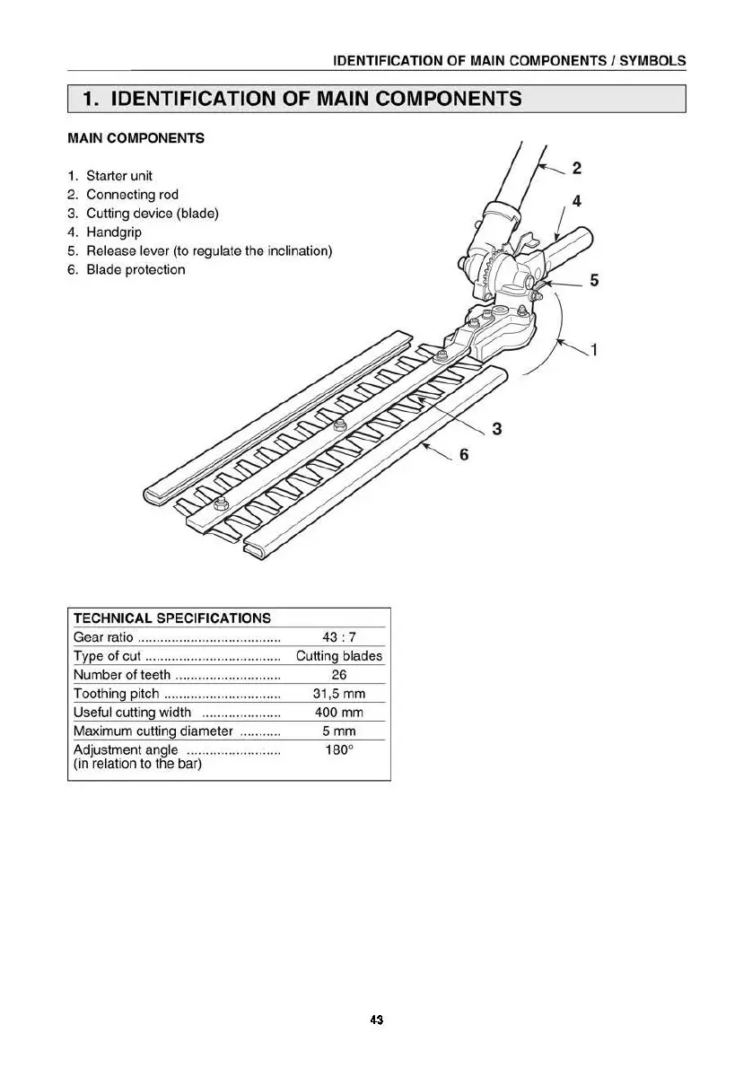
MAIN COMPONENTS
1. Starter unit
2. Connecting rod
3. Cutting device
(blade)
4. Handgr
ip
5. Release lever (to regulate the inclination)
6.
Blade protection
3
6
TECHNICAL SPECIFICATIONS
Gear ratio ..... ...... ..... ........ ...... ......
..
43
: 7
Type
of
cut .. ....... ............ ....
..
....... .. Cutting blades
Num
ber
of te
et
h ............................
26
Toothing pitch ............................... 31,5 mm
Useful cutting width . ... . . . . . . .. . . .
..
. . . .
400
mm
Maximum cutting diameter
..
...
..
.... 5 mm
Adjustment
angle ........... ..... . ..... ... 180°
(in relation to the bar)
43