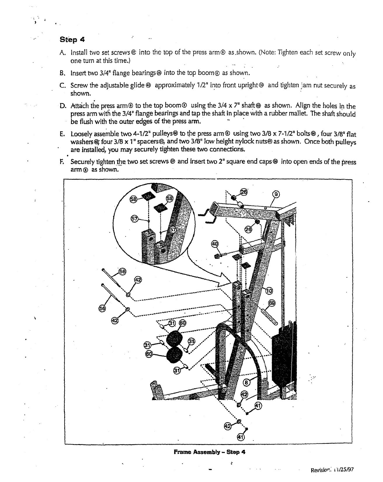
s~ep 4
Install two set screws@ into the top of the press arm@ as.shown. (Note: Tighten each set screw only
one turn at this time.)
B. Insert two 3/4" flange bearings~ into the top boom® as shown.
C.
Screw the adjustable glide @ approximately 1/2" into front upright@ and tighten i,am nut securely as
shown,
D.
Attach tt~e press arm@ to the top boom@ using the 3/4 x 7" shaft@ as shown. Align the holes in l:he
press arm witl~ the 3/4" flange bearings and tap the shaft in place With a rubber mai]et. The shaft st~ould
be flush with the outer edges of the press arm. "
Eo
Loosely assemble two 4-1/2" pulleys@ to the press arm ® using two 3/8 x 7-1/2" bolts@, four 3/8" fiat
washers~; feur 3/8 x 1" spacers®, and two 3t8" low height nylock nuts® as shown. Once both pulleys
are installed1 you may securely tighten these two connections.
F.
Securely tighten.t_he two set screws @ and insert two 2" square end caps@ into open ends of the press
arm ® as shown.
Revision.; ~’1/25/97
 Loading...