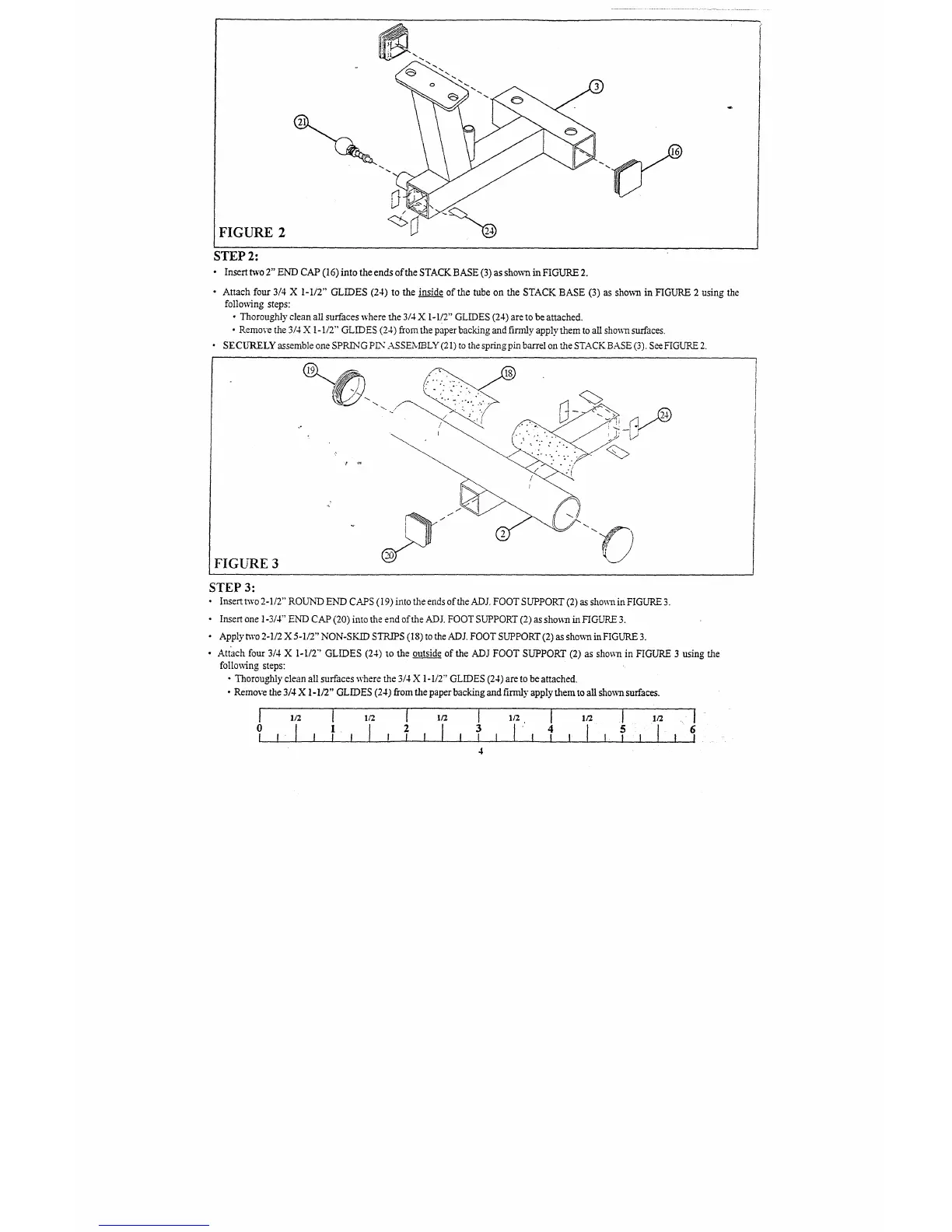
FIGURE 2
STEP 2:
¯ Insert two 2" END CAP (16) into the ends of the STACK BASE (3) as shown in FIGURE
¯
Attach fou~ 3/4 X 1-1/2" GLIDES (24) to the inside of the tube on the STACK BASE (3) as shown in FIGURE 2 using the
following steps:
¯
Thoroughly clean all surfaces where the 3/4 X 1-1/2" GLIDES (24) are to be attached.
¯
Remove the 3/4 X 1-1/2" GLIDES (24) from the paper backing and firefly apply them to all shown surfaces.
SECURELY assemble one SPRh-NG PLY" ASSEN~LY (21) to the spring pkn barrel on the STACK BASE (3). See FIGUP~
FIGURE 3
STEP 3:
¯
Insert two 2-1/2" ROUND END CAPS (19) into the ends of the ADJ. FOOT SUPPORT (2) as shown in FIGURE
¯
Insert one 1-3/4" END CAP (20) into the end of the ADJ. FOOT SUPPORT (2) as sho~:n in FIGURE
¯
Apply m’o 2-1/2 X 5-1/2" NON-SKID STR.~S (18) to the ADJ. FOOT SUPPORT (2) as shown in FIGURE
¯ Attach four 3/4 X 1-1/2"’ GLIDES (24) so the outside of the ADJ FOOT SUPPORT (2) as shoss~ in FIGURE 3 using the
follo~s4ng steps:
¯
Thorou~ly clean all surfaces where the 3/4 X 1-I/2" GLIDES (24) are to be attached.
¯
Remove the 3/4 X 1-1/2" GLIDES (24) from the paper backing and firmly apply them to all sho~ surfaces.
] ,/2 1’ l~z [ ~/’z I ~/~. [ l~z [ .I/2 ....
0
1.
2
3
[’ 4
5
6
4
 Loading...