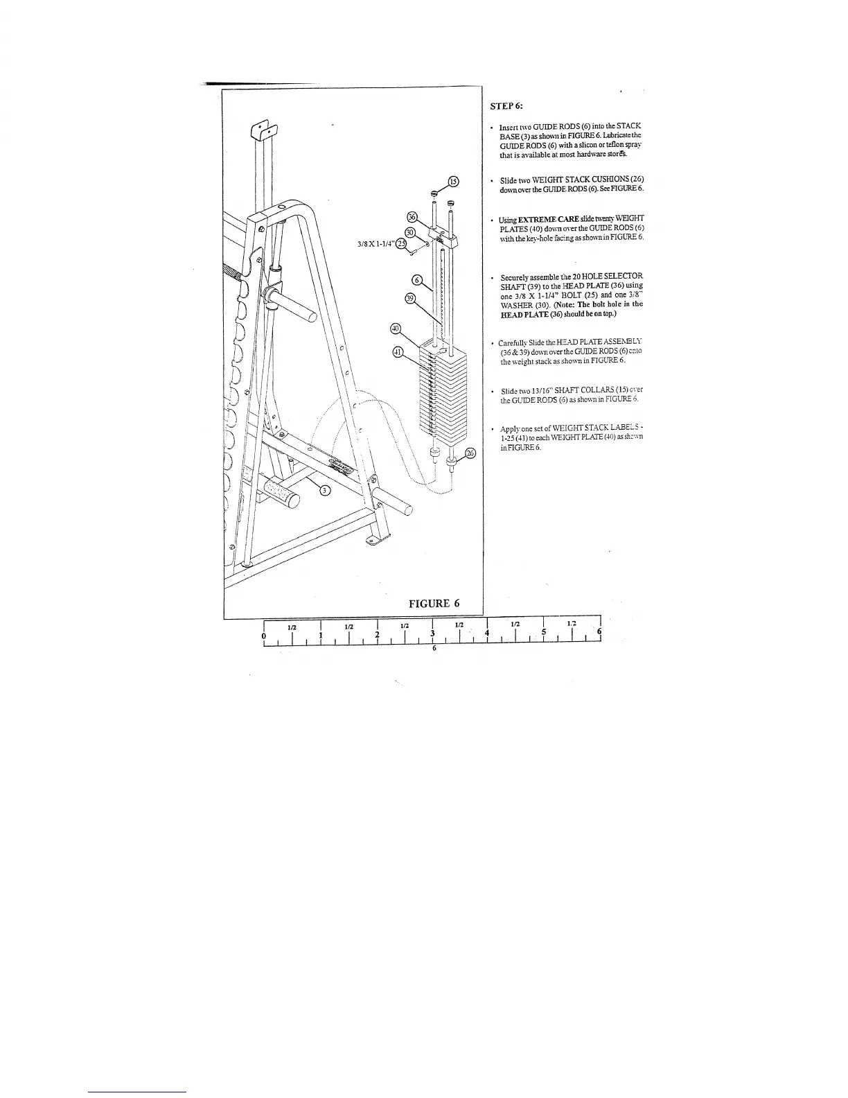
FIGURE 6
STEP 6:
Insert two GUIDE RODS (6) imo the STACK
BASE (3) as sho~ai in.FIGURE 6. Lubricate the
GUIDE RODS (6) with a slicon or teflon spray
that is available at most hard~are stor~s.
¯
Slide two WEIGftT STACK CUSHIONS (26)
dox~ over the GUIDE RODS (6). See HGURE
Using EXTREI~[F, GKRE slide t~m~t3." WEIGHT
PLATES (40) down over the GUIDE RODS (6)
with the key-hole facq~g as .~hownin FIGLqLE 6.
Securely assemble £~te 20 HOLE SELECTOR
SHAFT (39) to the HEAD PLATE (36) using
one 3/8 X 1-1/4" BOLT (25) and one 3/8"
WASHER (30). (Note: The bolt hole in
HEAD PLATE (36) should be on top.)
CarefuIly Slide ~e IKE.a39 PLATE AS SE~X~ LY
(36 & 39) do~ over the GUIDE RODS (6)
the weight stack as :;hown in FIGLqLE 6.
¯
Slide two 13116" SFLA~T COLLASL5 (15) over
~e GUIDE RODS (6) as sho~wt ~ FIGURE
Apply one set of WFIGHT STACK L~EL5 -
1-25 (41) to each WEIGHT PLATE (40) as sh:’a-n
inFIGURE 6.
4
I
 Loading...