7
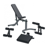
STEP 4:
FIGURE 4
0
1
2
345
6
1/2 1/2 1/2 1/2 1/2 1/2
• Attach eight 1 X 1” GLIDES (15) to the ends the CARRIAGE (6) as shown in FIGURE 4 using the following steps:
• Thoroughly clean all surfaces where the 1 X 1” GLIDES (15) are to be attached.
• Remove the 1 X 1” GLIDES (15) from the paper backing and firmly apply them to all shown surfaces.
• Attach one 1-1/4” SQ. RUBBER BUMPER (17) to the underside of the angle on the CARRIAGE (6) as shown in FIGURE 4.
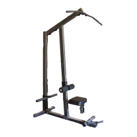
STEP 5:
FIGURE 5
• CAREFULLY slide the CARRIAGE (6) over the UPRIGHT (1) as shown in FIGURE 5.
• Insert one 3 X 2” END CAP (13) into the end of the UPRIGHT (1). See FIGURE 5.
6
1
13
15
17
6
 Loading...