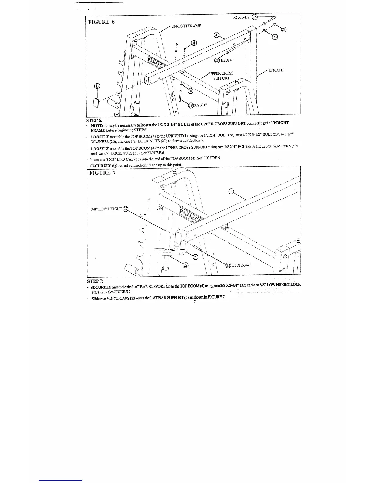
FIGURE 6
l/2 X 4"
SUPPORT
STEP 6:
¯ NOTE: It may be necessary to loosen the 1/2 X 3-1/4" BOLTS of the UPPER CROSS SUPPORT connecting the UPRIGITr
FRAME before beginningSTEP 6.
¯ LOOSELY assemble the TOP BOOM (4) to the UPKIGHT (1) using one 1/2 X 4" BOLT (28), one 112 X 3-1/2" BOLT (25),
"
97
~VASHERS (26), and one 1/2 LOCK NL-I-S (.,) as sho~t in FIGURE
¯ LOOSELY assemble the TOP BOOM (4) to the UPPER CROSS SUPPORT using t~vo 3/8 X 4" BOLTS (38).~ four 3/8"’ WASHERS
and two 318" LOCK NUTS (31). See FIGURE
¯
Insert one 3 X 2" END CAP (13) imo the ~d of the TOP BOOM (4). See FIGURE
SECURELY tighten all connections made up to this point.
FIGURE 7
 Loading...