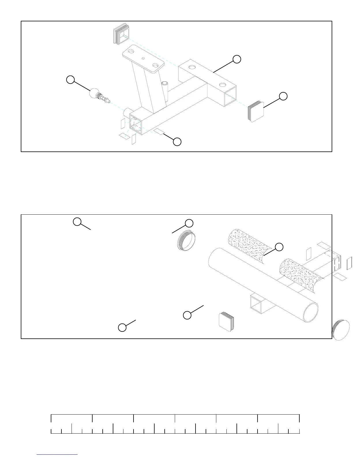
STEP 2:
FIGURE 2
• Insert two 2” END CAP (16) into the ends of the STACK BASE (3) as shown in FIGURE 2.
• Attach four 3/4 X 1-1/2” GLIDES (24) to the inside of the tube on the STACK BASE (3) as shown in FIGURE 2 using the
following steps:
• Thoroughly clean all surfaces where the 3/4 X 1-1/2” GLIDES (24) are to be attached.
• Remove the 3/4 X 1-1/2” GLIDES (24) from the paper backing and firmly apply them to all shown surfaces.
• SECURELY assemble one SPRING PIN ASSEMBLY (21) to the spring pin barrel on the STACK BASE (3). See FIGURE 2.
21
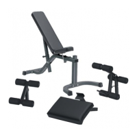
STEP 3:
FIGURE 3
• Insert two 2-1/2” ROUND END CAPS (19) into the ends of the ADJ. FOOT SUPPORT (2) as shown in FIGURE 3.
• Insert one 1-3/4” END CAP (20) into the end of the ADJ. FOOT SUPPORT (2) as shown in FIGURE 3.
• Attach four 3/4 X 1-1/2” GLIDES (24) to the outside of the ADJ FOOT SUPPORT (2) as shown in FIGURE 3 using the
following steps:
• Thoroughly clean all surfaces where the 3/4 X 1-1/2” GLIDES (24) are to be attached.
• Remove the 3/4 X 1-1/2” GLIDES (24) from the paper backing and firmly apply them to all shown surfaces.
• Apply two 2-1/2 X 5-1/2” NON-SKID STRIPS (18) to the ADJ. FOOT SUPPORT (2) as shown in FIGURE 3.
16
24
3
5
2
20
24
18
19
0
1
2
345
6
1/2 1/2 1/2 1/2 1/2 1/2