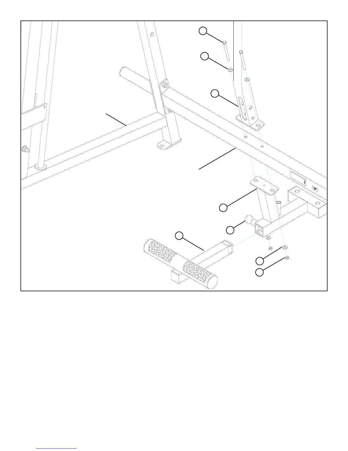
6
FIGURE 4
STEP 4:
• SECURELY assemble the STACK BASE (3) and the UPRIGHT (1) to the LOWER CROSS SUPPORT using two 3/8 X 4” BOLTS (38),
four 3/8” WASHERS (30), and two 3/8” LOW HEIGHT LOCK NUTS (29). See FIGURE 4.
3/8 X 4” 38
29
1
LOWER CROSS SUPPORT
3
UPRIGHT FRAME
30
30
• NOTE: It may be necessary to loosen the 1/2 X 3-1/4” BOLTS of the LOWER CROSS SUPPORT connecting to the UPRIGHT
FRAME before beginning STEP 4.
3/8”
LOW HEIGHT
LOCK NUT
2
21
• Pull back on the SPRING PIN (21) and CAREFULLY insert the ADJ. FOOT SUPPORT (2) into the STACK BASE (3) as shown in
FIGURE 4.