8
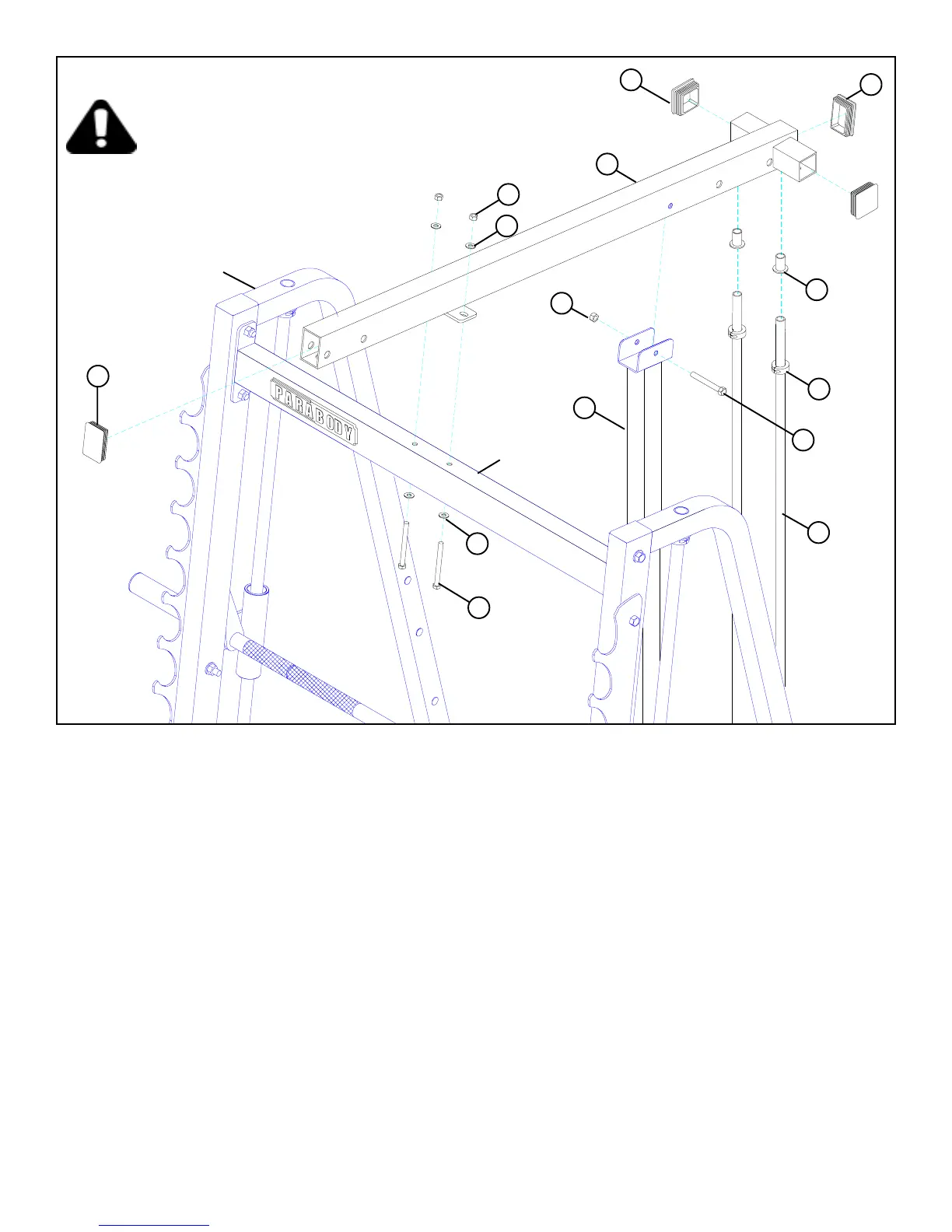
STEP 6:
FIGURE 6
• LOOSELY assemble the TOP BOOM (4) to the UPPER CROSS SUPPORT using two 3/8 X 4” BOLTS (38), four 3/8” WASHERS (30)
and two 3/8” LOCK NUTS (31). See FIGURE 6.
• Insert two 3 X 2” END CAPS (13) into the ends of the TOP BOOM (4). See FIGURE 6.
• SECURELY tighten all connections made up to this point.
38 3/8 X 4”
32 3/8 X 2-3/4”
4
27
30
30
13
UPRIGHT
UPPER CROSS
SUPPORT
• NOTE: It may be necessary to loosen the 1/2 X 3-1/4” BOLTS of the UPPER CROSS SUPPORT connecting the UPRIGHT
FRAME before beginning STEP 6.
• Slide the 13/16” SHAFT COLLARS (15) to the top of the GUIDE RODS (6) and SECURELY tighten the SHAFT COLLAR (15) set
screws. See FIGURE 6.
15
31
31
• Place TOP BOOM (4) over the GUIDE RODS (6) and LOOSELY assemble the TOP BOOM (4) to the UPRIGHT (1) using one 3/8 X 2-
3/4” BOLT (32) and one 3/8” LOCK NUT (31) as shown in FIGURE 6
• Insert two GUIDE ROD BUSHINGS (27) into the TOP BOOM (4) as shown in FIGURE 6.
13
16
1
6
• Insert two 2” SQ. END CAPS (16) into the ends of the TOP BOOM (4). See FIGURE 6.