9
0
1
2
345
6
1/2 1/2 1/2 1/2 1/2 1/2
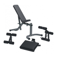
STEP 8:
FIGURE 8
• Route the 115-3/4” CABLE (12) through the TOP BOOM (4) as shown in FIGURE 8. (NOTE: It may be necessary to remove
the 3/8 X 2-3/4” BOLT to ensure CABLE is routed over the TOP of the BOLT.)
• SECURELY assemble three 3-1/2” PULLEYS (9) into the slots of the TOP BOOM (4) using three 3/8 X 2-3/4” BOLTS (32), six 3/8” FLANGE
SPACERS (33), and three 3/8” LOCK NUTS (31) as shown in FIGURE 8. (NOTE: Make sure the cable is routed over all the
pulleys.)
3/8 X 2-3/4” 32
9
4
12
33
31
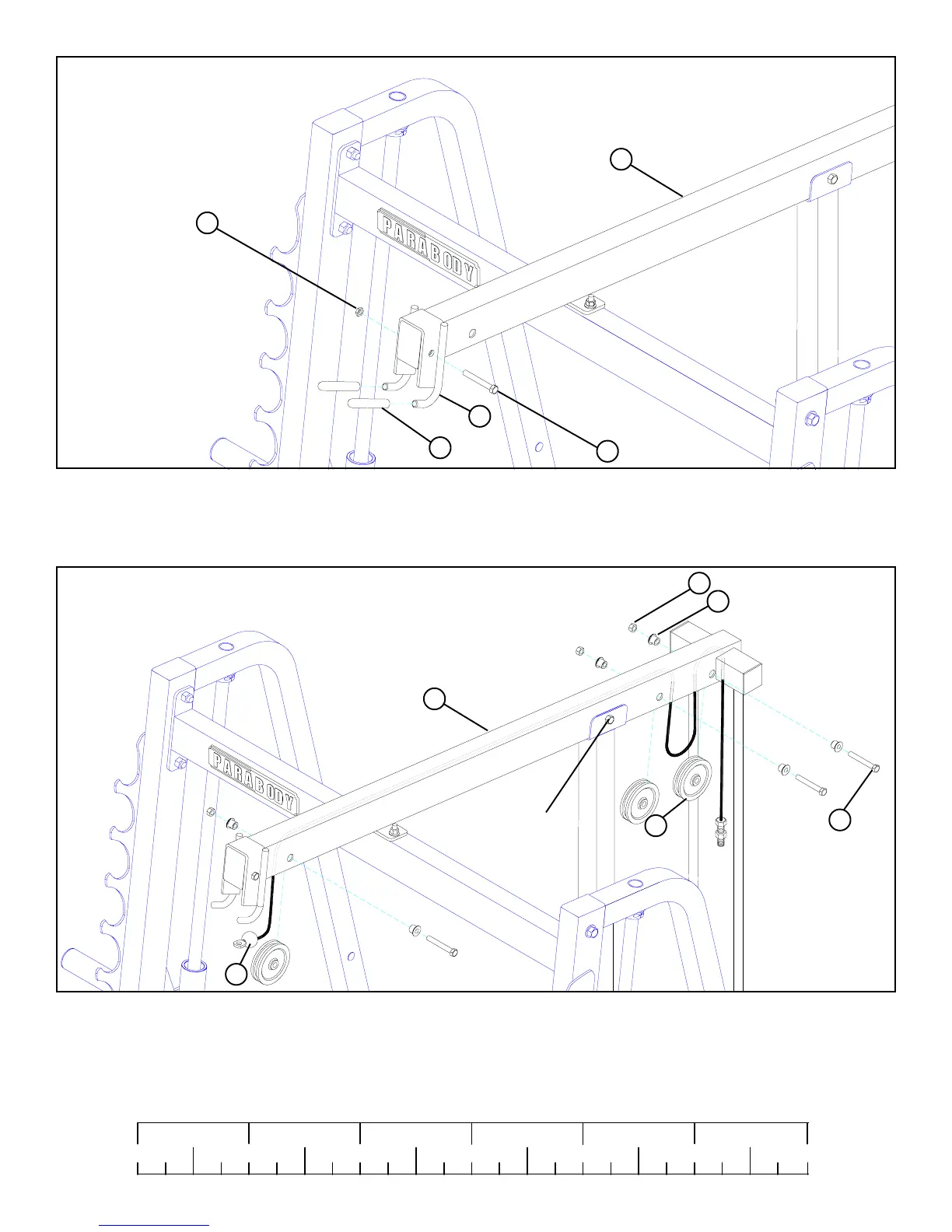
STEP 7:
FIGURE 7
• Slide two VINYL CAPS (22) over the LAT BAR SUPPORT (5) as shown in FIGURE 7.
• SECURELY assemble the LAT BAR SUPPORT (5) to the TOP BOOM (4) using one 3/8 X 2-3/4” (32) and one 3/8” LOW HEIGHT LOCK
NUT (29). See FIGURE 7.
32 3/8 X 2-3/4
3/8” LOW HEIGHT 29
22
4
5
Make sure CABLE
is routed over bolt!
• SECURELY retighten the removed 3/8 X 2-3/4” BOLT from the above step.