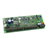
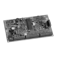
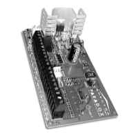
TELEPHONE LINE CONNECTION
Connect the incoming telephone company wires into "TIP" and "RING". Wires should then be run from "T1"
and "R1" to the installation's phone system.
POWERING UP THE UNIT
GENERAL
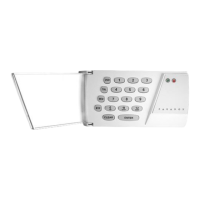
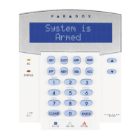
When keypads are installed far from the control panel, a keypad should be temporarily connected close
to the panel to conduct "power-up" testing. Connect the transformer. After 5 seconds, begin testing the
unit. Enter random commands on the keypad. It should "beep" in response to these commands. Open a
zone to ensure that keypad and panel are responding to signals. If the keypad does not respond and if no
indicator lights illuminate, check for AC voltage at the “AC” terminals. If 16VAC is flowing, then keypad
wiring should be verified. Also check for a short between "black" and "red' keypad wires.
PANEL PROGRAMMING METHODS
To conduct panel programming, use the keypad or initiate communication with Espload (see page 21).
Use of
Espload
is highly recommended, as it greatly reduces the potential for data entry errors during
programming. For Keypad Programming, see "Programming Guide".
BATTERY HOOK-UP (required on UL/ULC installation)
Warning: Do not connect transformer or battery until all wiring is completed. Use a 12VDC 7AH
rechargeable acid/lead or gel cell battery. Connect "red" battery lead to positive battery terminal, and
"black" battery lead to negative battery terminal. Reversed connections will blow the battery fuse. Battery
should not be connected until AC panel connections have been made. After connecting battery [TRBL]
key should illuminate. Pressing [TRBL] causes key [8] to illuminate (trouble indicator for "timer loss"). (See
"Trouble Display Monitoring" section, p. 18-19)
BATTERY TEST
The panel verifies battery connection every 60 seconds. If the battery is not connected, trouble indicator
key [1] illuminates. If battery is connected, a 4 second test of battery under load is conducted. Every
hour, a 64 second battery test will be carried out (not applicable to software versions 1.4 and beyond).
Panel arming can be blocked if the battery test fails, if programmed. Test failure causes trouble indicator
key [1] to illuminate, indicating that battery capacity is insufficient. When the panel runs on battery power,
with or without AC, if battery voltage drops to 10.5 volts, trouble indicator key [1] will illuminate. (If pro-
grammed, a trouble report code will also be sent to the central station.) At 8.5 volts all outputs are closed.
ZONE WIRING CONFIGURATIONS AND OPTIONS
The selection of the panel (number of zones) should be based on the requirements of a security installation.
LOOP CONFIGURATIONS AND ZONE CONNECTIONS
Single zones can be configured for N.C. contacts without EOL, or zone resistors (see Fig. 1, page 10). By
using 1 zone resistor, single zones can be configured for N.C. and/or N.O. contacts (see Fig. 2, page 10).
A single zone can also be configured to detect alarm and tamper (tamper will transmit a separate distinct
signal and cause the zone light at the keypad to flash) see Fig. 3, page 11.
Note: Configuring zones in single zone mode reduces number of available zones. (728L, 728, 738,
748)
By utilizing 2 zone resistors (see "Typical", pg. 10) each loop (pair of wires) will recognize two distinct alarm
zones for N.C. contacts. A separate "tamper" signal can also be transmitted and displayed on the keypad
(flashing zone light). Adding a green (1K OHM) EOL resistor will provide loop supervision (see Fig. 4, pg. 11).
Notes:
1) Two zones per loop configuration reduces wiring and installation requirements by permitting the
connection of two distinct zones per input (loop), on the same pair of wires. Coverage is not compro-
mised in any way. Each zone can be reported separately, based on different resistor values, and the
same pair of wires can also provide "anti-tamper" and "wiring failure" recognition. In order to have
Advanced Technology Zones, enable at address 210, key [8].
2) The input terminals are marked with 2 digits ex. 1/4, 1/13. These digits indicate the two zones that
are associated with that input when ATZ (zone doubling) is used. Two resistors are required when ATZ is
operational.The first digit (regular zone) is identified by a green (1K ohm) resistor, and the 2nd digit (dou-
bled zone) is identified by a brown (.5K ohm) resistor.
9
IM8

 Loading...


