IP150 Internet Module
Installation Manual V1.3
IP150-EI03 03/2016
Description
The IP150 Internet Module is an HTTPs-supported IP communication device that enables you to control and
monitor your security system through any web browser (e.g., Google Chrome). The IP150 provides freedom to
access your system and receive instant, SSL encrypted email notifications anywhere in the world when your
system detects activity. So no matter where you are, you will have access to arm, disarm, and more.
Before You Begin
Before you begin, make sure you have a web-enabled computer. You will also require the following in order to
configure your IP150 Internet Module:
• Ethernet-compatible computer with internet access (required for remote access)
• Router
• 4-pin serial cable (included)
• CAT5 Ethernet cable (maximum 90m (295 ft.), not included)
• Paradox IP Exploring Tools Software (required for remote access). Software can be downloaded from
www.paradox.com.
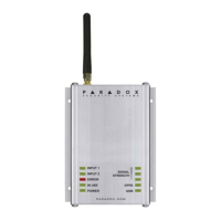
Figure 1 - IP Communication Overview
Connecting and Installing the IP150
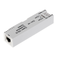
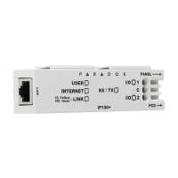
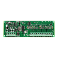
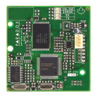
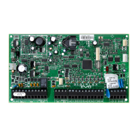
Figure 2 - IP150 Overview
To connect and install the IP150:
1) Connect the 4-pin serial cable between the panel’s serial connector and the IP150’s panel connector (refer to
Right Side View in Figure 2).
2) Connect the Ethernet cable between the router and the IP150’s network connector (refer to Left Side View in
Figure 2).
3) The on-board LEDs will illuminate to indicate the IP150’s status (refer to Front View in Figure 2).
4) Clip the IP150 to the top of the metal box (refer to Metal Box Installation in Figure 2).
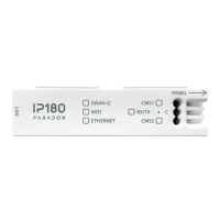
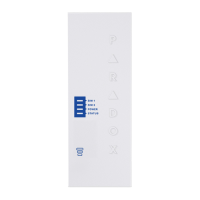
LED Indicators
Reset IP150 to Default
To reset the IP150 module to its default settings, insert a pin/straightened paper clip (or similar) into the pin hole
located between the two I/O LEDs. Press down gently until you feel some resistance; hold it down for
approximately 5 seconds, release it when the I/O and RX/TX LEDs start flashing, and then press it again. The I/O
and RX/TX LEDs will remain lit during the reset.
IP Reporting
When using IP reporting, the IP150 has the ability to poll the monitoring station. To enable IP reporting, the IP150
must first be registered to the monitoring station’s IP Receiver (IPR512). Telephone reporting can be used in
conjunction with, or as a backup to IP reporting. Before registering the IP150, the following information must be
obtained from the monitoring station:
• Account number(s) - One account number for each partition used. IP/GPRS reporting uses a different set of
account numbers than those used for dialer reporting.
• IP address(es) - (12-digit number e.g., for 195.4.8.250 you must enter 195.004.008.250).
• The IP address(es) indicate(s) which of the monitoring station’s IP Receivers will be used for IP reporting.
• IP port(s) (5-digit number; for 4-digit numbers, enter 0 before the first digit). The IP port refers to the port
used by the monitoring station’s IP Receiver.
• Receiver password(s) (up to 32-digits).
• The receiver password is used to encrypt the IP150 registration process.
• Security profile(s) (2-digit number). The security profile indicates how frequently the monitoring station is
polled by the IP150. Security profile numbers and polling frequency are defined by the monitoring station.
Setting Up IP Reporting
1) Ensure the panel’s report code format is set to Ademco Contact ID:
MG/SP: section [810]
EVO: section [3070]
2) Enter the IP reporting account numbers (one for each partition):
MG/SP: section [918] / [919]
EVO: section [2976] to [2983]
3) In the General IP Options section, set up IP line monitoring options and dialer options, and ensure IP
reporting is enabled (refer to the following tables).
NOTE: When the IP150 is connected to a UC300, setting up IP reporting is performed through BabyWare.
LED
Description
User On when a user is connected
Internet
LED Status Internet Connection ParadoxMyHome Enabled
On Connected Connected
Flashing Connected No connection
Off No connection No connection
LED Status Internet Connection ParadoxMyHome Disabled
Off N/A No connection
Link Solid Yellow = Valid Link @ 10Mbp
Solid Green = Valid Link @ 100Mbp
LED will flash according to data traffic
Flashing Yellow/Green = DHCP trouble
Rx/Tx On after first successful communication exchange
Flashes when data is transmitted or received through/from panel
Off when no connection has been established
I/O 1 On when activated
I/O 2 On when activated
MG/SP: section [806]
EVO: section [2975]
4) Enter the monitoring station’s IP address(es), IP port(s), receiver password(s), and security profile(s)
(information must be obtained from the monitoring station).
5) Register the IP150 module with the monitoring station. To register, enter the sections below and press [
ARM].
The registration status is displayed as well as any registration errors.
NOTES:
1. An IP150 used with an MG/SP system will always poll using the partition 1 IP account number. When using
an EVO system, the partition 1 IP account is used by default, but can be defined in section [3020]. All reported
system events will originate from the partition selected in this section.
2. When the IP150 is connected to a UC300, setting up IP reporting is performed through BabyWare.
Remote Access
The IP150 provides remote access to control and monitor a security system via web browsers or PC
software. This provides the user with the freedom to access the system from anywhere in the world. The following
steps will guide you in setting up remote access.
Step 1: Setting up the Router
This step allows you to set up the router so that the IP150 module can function properly.
1) Ensure the router is connected properly as indicated in the router’s instructions.
2) Access your router’s configuration page. Refer to your router’s manual for the exact procedure.
In most cases, this is done by entering the router’s static IP address in the address bar of your
Web browser. For this instance, we will use 192.168.1.1 as an example for the router’s IP
address that may be indicated in the router’s instructions or on a sticker on the router.