EasyManua.ls Logo

Paradox ZX8 - User Manual

Paradox ZX8
2 pages
Print Icon
To Next Page IconTo Next Page
Loading...
8-Zone Expansion Modules
ZX8
V6.0
Instructions / Instrucciones
PARADOX.COM
Printed in Canada - 05/2014
Figure 1: ZX8 Connections
The 8-zone Expansion Module (ZX8) is an interface between the control
panels and any hardwired detection devices. The ZX8 connects to the
control panel's combus to provide eight additional hardwired inputs
and one 50mA on-board PGM output.
Specifications
Installation
Connect the module as shown in Figure 1.
Table 1: Jumper Setting
Table 2: Illustration
Digiplex +Digiplex EVO
A “Locate” request coming from the control panel can be disabled by pressing the “Disable Locate.
MG/SP Series
Press the “Disable Locate” for 3 seconds. Fast flash of the green LED occurs. Jumper settings can be changed.
Green “LOC” LED
Digiplex and Digiplex EVO
Remains Illuminated during power up
Flashes fast to indicate it is receiving a “Locate” request from the control panel. To disable a “Locate” request, press the “Disable Locate” switch.
SP Series and MG5050
Flashes fast to indicate a change in jumper setting.
Red “WDG” LED
All panels
Flashes to indicate proper operation
If both “LOC and the “WDG LED are flashing alternately, the module is
experiencing a communication failure with the control panel.
Connect the detection devices to the ZX8 input terminals exactly as shown in the appropriate control panel’s Programming Guide.
Digiplex y Digiplex EVO
Z8: Input terminal Z8 can be used as an anti-tamper switch input. Enable
section [001] option [1]
MG/SP Series
Z1: Input terminal Z1 can be used as an anti-tamper switch input. Enable
section [706] option [4] for panel+1, option [5] for panel+9 and option [6] for panel+17
Input voltage: Typically 12 to 16 Vdc
Current cons.: 28mA
Max.# of ZX8: max.3: MG/SP Series
No. of outputs: One 50mA PGM
No. of inputs: 8 inputs
No. of zones: 8 standard zone inputs
Oper. temperature: -20ºC to 50ºC (-4ºF to 122ºF)*
Compatibility: Any Digiplex or Digiplex EVO series control panel
Any SP Series control panel (V2.0 or higher)
MG5000/MG5050 control panels (V2.0 or higher)
WinLoad Software V2.03 or higher
NOTE: For 1728/1738 compatibility, refer to the
SP-ZX8 instructions.
MG5000
(2 on-board zones)
MG5050
(5 on-board zones)
SP4000
(4 on-board zones)
SP5500
(5 on-board zones)
SP6000
(8 on-board zones)
SP65
(9 on-board zones)
SP7000
(16 on-board zones)
No/
ATZ
ZTA
With/
ATZ
ZTA
No/
ATZ
ZTA
With/
ATZ
ZTA
No/
ATZ
ZTA
With/
ATZ
ZTA
No/
ATZ
ZTA
With/
ATZ
ZTA
No/
Sin/Sans
ATZ
ZTA
With/
Con/Avec
ATZ
ZTA
No/
Sin/Sans
ATZ
ZTA
With/
Con/Avec
ATZ
ZTA
No/
Sin/Sans
ATZ
ZTA
With/
Con/Avec
ATZ
ZTA
zones/ zones/ zones/ zones/ zones/ zones/ zones/z
A / Panel+1*
3-10 5-12 6-13 11-18 5-12 9-16 6-13 11-18 9-16 17-24 10-17 19-26 17-24 -
B / Panel+9*
11-18 13-20 14-21 19-26 13-20 17-24 14-21 19-26 17-24 25-32 18-25 27-32 25-32 -
C / Panel+17*
19-26 21-28 22-29 27-32 21-28 25-32 22-29 27-32 25-32 - 26-32 - - -
*Press “Disable Locate” for 3 seconds to change jumper setting
A
B
C
D
External
Anti-Tamper
Switch (N.C.)
ZX8-TI03
All manuals and user guides at all-guides.com
all-guides.com

Other manuals for Paradox ZX8

Question and Answer IconNeed help?

Do you have a question about the Paradox ZX8 and is the answer not in the manual?

Summary

ZX8 Module Specifications

Input Voltage Range

Specifies the typical input voltage for the ZX8 module.

Current Consumption

Details the current draw of the ZX8 module.

Maximum Module Capacity

Indicates the maximum number of ZX8 modules supported by certain panel series.

On-board PGM Output

Describes the single 50mA PGM output available on the module.

Zone and Input Count

Specifies the number of inputs and standard zone inputs provided by the ZX8.

Operating Temperature

Defines the operational temperature range for the ZX8 module.

System Compatibility

Lists control panel series and software versions compatible with the ZX8 module.

ZX8 Module Installation and Connections

Module Connection Diagram

Illustrates how to connect the ZX8 module to the control panel's combus.

ZX8 Module LED Indicators

LOC LED Behavior

Explains the functionality and indications of the LOC LED for different panel types.

WDG LED Behavior

Describes the behavior of the WDG LED, indicating proper operation or failures.

ZX8 Input Terminal Functions

Anti-Tamper Input Configuration

Details how input terminals Z8 (Digiplex/EVO) or Z1 (MG/SP) can function as anti-tamper switches.

Programming ZX8 Module Options

Tamper Recognition and PGM Settings

Configuration options for tamper recognition and PGM deactivation/normal state.

PGM Base Time Selection

Setting the base time for PGM events, affecting timing accuracy.

Input Speed and Time Value

Configuring input speed response and specific time values for zone inputs.

PGM Activation and Deactivation Events

Defining events that trigger PGM activation or deactivation, using event groups.

PGM Test Mode

Enabling a test mode to verify PGM functionality for 8 seconds.

EOL and ATZ Configuration

Setting End of Line (EOL) and Anti-Tamper (ATZ) options for individual zone inputs.

Selectable Input Resistors

Choosing resistor values for EOL and contact detection for zone inputs.

SP Series Programming Options

Specific programming sections for Tamper Recognition, Zone Assignment, and PGM settings in SP series.

Overview

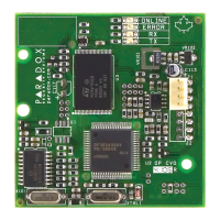
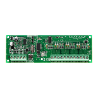
The Paradox ZX8 is an 8-zone Expansion Module designed to interface between Paradox control panels and hardwired detection devices. It connects to the control panel's combus to provide eight additional hardwired inputs and one 50mA on-board PGM output. This module is essential for expanding the zone capacity of compatible security systems, allowing for a greater number of detection devices to be integrated into the system.

Function Description:

The primary function of the ZX8 is to expand the number of available zones on a compatible Paradox control panel. Each ZX8 module adds eight standard zone inputs, enabling the connection of various hardwired detection devices such as motion detectors, door/window contacts, and glass break sensors. In addition to zone expansion, the module also provides a single 50mA PGM (Programmable Output) output. This PGM can be programmed to activate or deactivate based on specific system events, offering flexibility for controlling external devices like sirens, strobes, or other automation components. The ZX8 acts as a bridge, translating signals from the hardwired devices into a format understood by the control panel via the combus.

Important Technical Specifications:

  • Input Voltage: Typically 12 to 16 Vdc.
  • Current Consumption: 28mA.
  • Maximum Number of ZX8 Modules: Up to 3 for MG/SP Series control panels.
  • Number of Outputs: One 50mA PGM.
  • Number of Inputs: 8 inputs.
  • Number of Zones: 8 standard zone inputs.
  • Operating Temperature: -20°C to 50°C (-4°F to 122°F).
  • Compatibility:
    • Any Digiplex or Digiplex EVO series control panel.
    • Any SP Series control panel (V2.0 or higher).
    • MG5000/MG5050 control panels (V2.0 or higher).
    • WinLoad Software V2.03 or higher.
    • For 1728/1738 compatibility, refer to the SP-ZX8 instructions.

Usage Features:

The ZX8 offers several features that enhance its usability and integration into a security system:

  • Zone Configuration: The module supports various zone configurations, including EOL (End-of-Line) and ATZ (Advanced Technology Zone) options. Jumper settings on the module determine the starting zone numbers for the expanded zones, which can be adjusted based on the specific control panel model and whether ATZ is enabled. For example, on an MG5000 panel with ATZ, the ZX8 can provide zones 5-12, 13-20, or 21-28 depending on the jumper setting.
  • PGM Programming: The on-board PGM can be extensively programmed through the control panel's software. Users can define activation and deactivation events based on various criteria, such as event groups, feature groups, or specific zone inputs. A PGM timer allows for setting the duration of the PGM's activation, with a base time selection (15 milliseconds, 1 second, or 1 minute) and a time value (000-255). A PGM test mode is available to verify its functionality.
  • Input Speed Configuration: The input speed for each zone can be configured, allowing for customization based on the type of detection device connected. This is done through even-numbered sections for base time selection (000-002) and odd-numbered sections for the time value (000-255), which is multiplied by the base time.
  • Selectable Input Resistor: The ZX8 allows for selectable input resistors for EOL and contact configurations, with options for different resistor values (e.g., 1K, 2K2, 3K3, 4K7, 6K8, 8K2). This flexibility ensures compatibility with a wide range of detection devices and helps in meeting specific installation requirements.
  • Tamper Recognition: The module supports tamper recognition, which can be enabled for EOL zones or for specific zone inputs (e.g., Z1 or Z8). This feature adds an extra layer of security by detecting attempts to tamper with the wiring or the device itself.
  • Locate Functionality: The "Locate" function helps in identifying the module during installation or troubleshooting. The green "LOC" LED on the module indicates its status: illuminated during power-up, or flashing fast when receiving a "Locate" request from the control panel. This request can be disabled by pressing the "Disable Locate" switch on the module.
  • Anti-Tamper Switch Input: For Digiplex and Digiplex EVO panels, input terminal Z8 can be configured as an anti-tamper switch input. For MG/SP Series panels, input terminal Z1 can be used for this purpose. This allows for an external anti-tamper switch to be connected, providing additional security against unauthorized access to the module or its enclosure.

Maintenance Features:

  • LED Indicators: The ZX8 includes two LED indicators:
    • Green "LOC" LED: Indicates the module's power status and "Locate" request status. A fast flash indicates a change in jumper setting for SP Series and MG5050 panels.
    • Red "WDG" LED: Flashes to indicate proper operation. If both "LOC" and "WDG" LEDs flash alternately, it signifies a communication failure with the control panel, aiding in quick diagnosis of connectivity issues.
  • Jumper Settings: Jumper settings are used to configure the module's zone numbering and ATZ options. These settings can be changed by pressing the "Disable Locate" switch for 3 seconds, which causes the green LED to flash fast, indicating that jumper settings can be adjusted.
  • Programming Method: The module's options and PGM settings are programmed through the control panel's programming interface. For Digiplex/EVO panels, this involves holding the [0] key + [INSTALLER CODE], entering section [953] (DGP-848) or [4003] (EVO), then the module's 8-digit serial number, and finally the desired section to configure options or data. For SP/Magellan panels, it involves [ENTER] + [INSTALLER CODE], then entering the section and turning options ON/OFF or entering data. This structured programming approach facilitates easy configuration and troubleshooting.
  • Wiring Connections: The module provides clear terminal blocks for connecting the combus (RED, BLK, GRN, YEL), PGM output, and zone inputs (Z1-Z8 with corresponding COM terminals). The wiring diagram in the manual illustrates how to connect the module to the control panel and external devices, ensuring correct installation.

Paradox ZX8 Specifications

General IconGeneral
BrandParadox
ModelZX8
CategoryControl Unit
LanguageEnglish

Related product manuals