Alarm Mode. To silence the Buzzer, press the SILENCE key, with the keyswitch in the
Control Enable position. All indications will remain ON until the Reset button is pressed.
Keypad buttons are active only when the keyswitch is turned to the Control Enable
position.
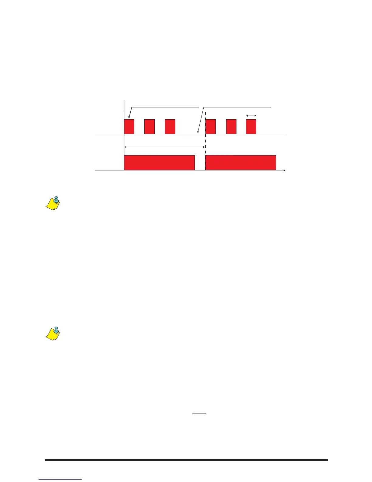
Figure 3 shows the alarm LED indications when activated by detectors, manual call
points and evacuation keyswitch.
Figure 3. Zones Alarm indications
Alarm LED indication will blink according to the main signalling device alarm output
pattern.
3. Central Electric Keyswitch
Coperations are accessed when the Electric Keyswitch is set to the appropriate position
(Figure 1). The central electric Keyswitch has three positions:
1
st
position (Access Level 1) Normal: This is the Normal operation mode. The panel
waits for alarm events or any faults that may develop in the installation. All buttons on the
silicon rubber keypad are disabled.
2
nd
position (Access Level 2) Control Enable: Alarm events and possible faults are
detected, all buttons on the silicon rubber keypad are active and the system is control-
lable.
For Normal operation the keyswitch must be in the 1
st
position.
3
rd
position (Access Level 3) Evacuate: After a small delay of approximately 2 sec-
onds all the system zones turn into Alarm Evacuation Mode resulting in the activation of
all signaling devices in the protected area. The sounder connected on the main board
gives a continuous sound. In case that a MER-8 relay module is used, the extra relays
are activated and connected sounders give an intermittent sound. The system returns
to standby mode by turning the key to the Control Enable position and pressing the
RESET button.
The key from the Keyswitch can be removed only when the keyswitch is in the Normal
position.