PARADOX.COM
PCS265L-EI06 03/2022
You must use a SIM card with a
data charge limit. Paradox will not
be responsible in any way for any
usage charges of data or voice
whatsoever.
Installation
SIM Card Connection
The PCS265LTE supports two nano LTE/4G/3G/2G or GSM provider
SIM cards. To install the SIM cards, open the SIM Card tray and insert
card into base, as shown. SIM 1 is used as “Primary” and SIM 2 for
“Backup”. If only one SIM card is used, insert into SIM 1.
Note: SIM Card 2 can only be configured via SMS.
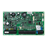
Panel Connections
Connect the PCS265LTE’s serial out to the serial connector on the
panel.
• For LTE/4G/3G/2G reporting, connect to the Serial port of
the panel.
• For GSM reporting, connect to the EBUS port of the panel.
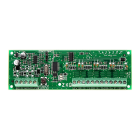
RS485 Connection
A CVT485 module can be connected onto the control panel’s EBUS in
order to lengthen the distance (up to 300 m. / 1000 ft.) between the
panel and the PCS265LTE. Refer to the drawing for connections.
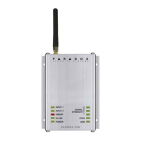
External Antenna Connection
Use the ANTK4G LTE external antenna kit for PTCRB installations or to
improve RF reception if your module’s signal strength is weak. External
antenna kits and extension kits are purchased separately.
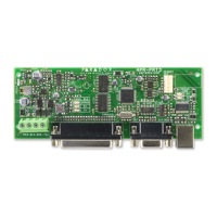
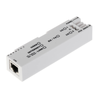
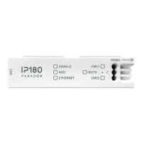
IP Module Connection
The PCS265LTE can be connected to an IP Internet Module’s PCS port.
For more information on how to configure this option, please refer to the
IP module’s Installation manual.
Powering-up the PCS265LTE
Once your hardware connections are completed, the PCS265LTE
module will begin its power up sequence.
• Power LED will turn solid green
• Status LED will turn solid green
• SIM card 1 LED will slowly flash red while searching for the GSM
network; once found the LED will be solid yellow
If configured for LTE/4G/3G/2G reporting, you will need to configure
network provider information. Refer to the Programming section.
Note: The battery is optional. If a battery is used/installed, do not allow
the battery to deplete and ensure that the battery is replaced when low.
The battery function is to support power shut down and not to be used
as backup as defined in EN50131-6.
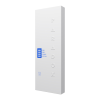
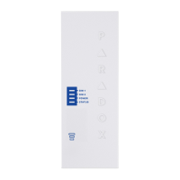
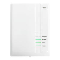
LED Functionality
*When using an e-bus connection, the LED is always yellow.
Programming
In order to configure the PCS265LTE for reporting, you will need to first
configure your SIM cards. Please note that SIM Card 1 can be
configured via panel programming or SMS and SIM Card 2 via SMS
only.
IP Reporting over LTE/4G/3G/2G and SMS Personal Reporting
Network Provider Information
Network Provider Information
Refer to the List of SMS Commands Table on page 2.
LTE/4G/3G/2G Reporting Options
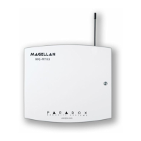
1 Mounting hole
2 Antenna connector
3 Wall tamper hole
4 Serial connector
5 RS485 / power terminal
6 Upgrade connector
7 Battery terminal
8 Cover tamper switch
3
4
5
6
7
2
1
8
1
GSM (EBUS Connector)
LTE/4G/3G/2G (Serial Connector)
CVT485
Up to 300m (1000 ft.)*
Up to 50m (160 ft.) AWG18
LED Functionality
SIM1 and
SIM2*
Solid yellow GSM
Red flashing No network
Solid blue LTE/4G
Internet present, polling to SWAN
and received a connection identifier
Flashing Blue Data exchange/updating firmware
Solid green 3G/2G
Internet present, polling to SWAN
and received a connection identifier
Flashing green Data exchange/updating firmware
Flashing every
0.2 seconds
Internet present, polling to SWAN but
did not receive a connection identifier
Flashing every
0.5 seconds
Internet present, received a
connection identifier but it is not
polling to SWAN
Flashing every
1 second
Internet present, not polling to SWAN
and did not receive a connection
identifier
Off No Internet connection
Power Solid green Power on
Off No power
Status
Red Error condition, no firmware
Green No error and/or battery fully charged
Orange Battery charging
Signal
Strength
Three LEDs indicate network signal strength
MG/SP EVO Feature
[921] [2960] APN part 1 (characters 1-16)
[922] [2961] APN part 2 (characters 17-32)
[923] [2962] APN user name part 1 (1-16)
[924] [2963] APN user name part 2 (17-32)
[925] [2964] APN password part 1 (1-16)
[926] [2965] APN password part 2 (17-32)
Important: This information can be obtained from your mobile
network provider.
MG/SP EVO Feature Details
[918]
[919]
[2976] to
[2983]
Account / Partition
Registration
MG/SP: Sections
represent account/
partition 1 and 2
EVO: Sections
represent account /
partition 1 to 8
PCS265LTE
LTE / 4G / 3G / 2G / GSM
Communicator Module
V5.0 or higher
Installation and Programming Guide
**Compatible with Insite GOLD
and SWAN Server**