Copyright 2021 © Paragon Tank Truck Equipment
•
The use of Paragon brackets is recommended.
•
Should be strong enough to support the P657, accessories, and torque required.
•
Must allow minimum of 3/4” clearance between the blower and frame rail to prevent damage to the
blower.
•
Use Qty (4), 5/8” diameter bolts to mount the P657 Mounting Bracket to the tractor frame rail.
•
Paragon strongly recommends consultation with a local drive shaft specialist PRIOR to drilling the tractor frame rail.
•
At a minimum a drive shaft specialist should verify the following:
-
Required length meets industry standards for safe operation at the desired rpm.
-
Drive shaft is capable of operations for the required rpm.
-
Equipment slopes are correct to minimize torsional vibrations.
-
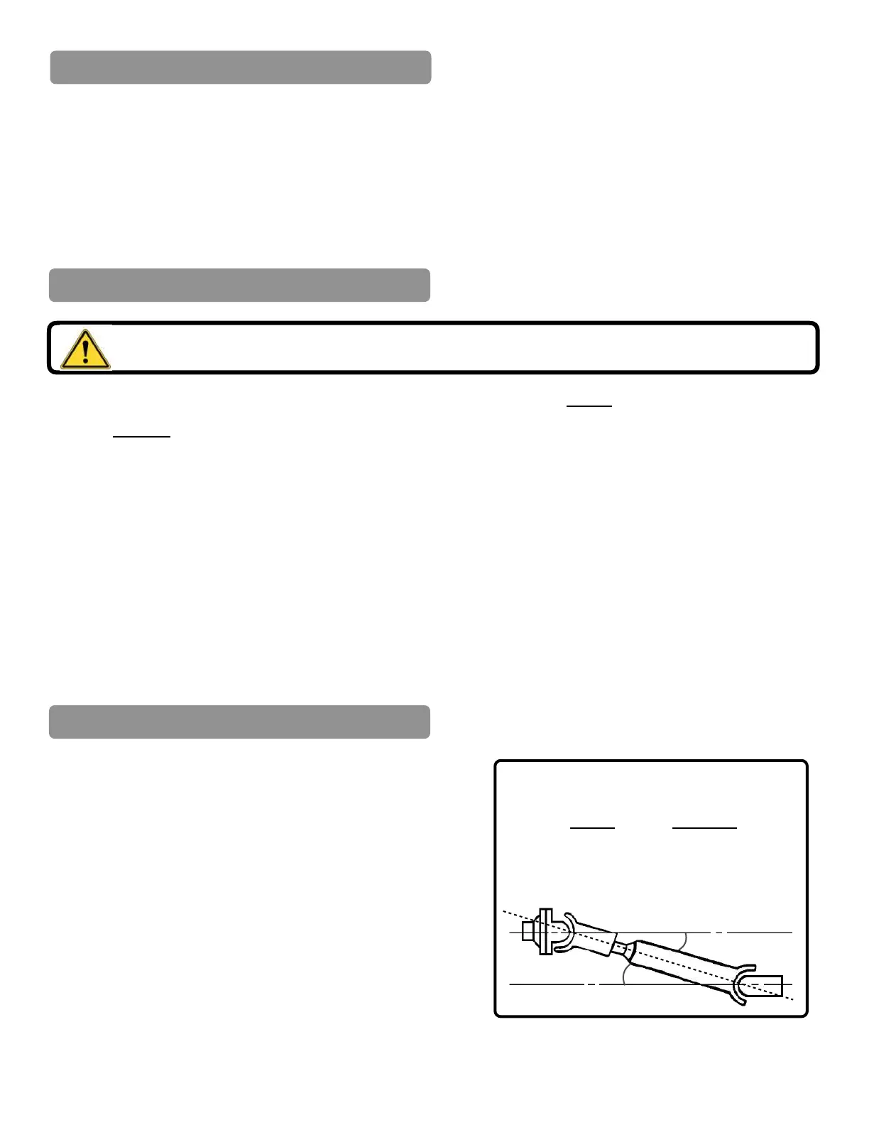
Confirm the drive shaft working angles are within industry specifications for safe operation(See Fig.4).
•
A minimum 3” diameter DOM Tubing x 0.083 wall thickness be used for P657 Blower applications.
•
That each drive shaft section has a “U” bolt hanger bracket for safety (See Fig.5, Page 8).
•
A minimum Drive Shaft critical speed of 2000 rpm.
•
Attach mounting bracket to the blower.
•
Torque mounting bolts to the required torque (77 lbs·ft)
•
Clamp the blower in place on the frame rail while
supporting the equipment from underneath.
•
Contact a drive shaft specialist.
Drive shaft and other components may shift with changes in suspension.
Maximum Drive Shaft Working Angles
Speed Angle “A”
2000 RPM 8°
1800 RPM 9.5°
1500 RPM 11.5°
1000 RPM 13°
Mounting Bracket Requirements
Determine Blower Mounting Slope