EasyManua.ls Logo

Park Systems XE-70 User Manual

Park Systems XE-70
10 pages
To Next Page IconTo Next Page
Page #1 background imageLoading...
Page #1 background image
Park XE-70 AFM User Manual
Ed Fei and Ryan Brock
Updated 10/30/13
NOTE: This document is intended as a quick reference for basic operation of the
Park XE-70 and is by no means a comprehensive manual. It is strongly suggested
that users look through the Park documentation. The better you understand the
instrument, the more effectively you will be able to use it.
Basic AFM Principles
When the tip is suspended in air, the laser will hit the center of the quadrant photodetector.
If the tip encounters a feature on the surface, the tip deflects and the laser will move on the
quadrant photodetector. This is relayed to a motor controlling the tip which adjusts the tip’s
vertical position until the laser is aimed in the center of the quadrant photodetector once again.
Effectively, this keeps the tip at a constant distance from the sample surface. By recording the
position of the motor height, we can now know the topography of the sample surface.
The tips provided in this lab are intended for ‘non-contact’ AFM, which is similar in principle to
what is described above. Rather than relying on physical contact with the surface, the
cantilever/tip is oscillated at a given frequency above the sample surface, and interactive forces
from the surface lead to changes in the amplitude/phase of this oscillation.
Setting up the AFM is simple: adjust the mirrors until the light path follows the diagram below
Question and Answer IconNeed help?

Do you have a question about the Park Systems XE-70 and is the answer not in the manual?

Park Systems XE-70 Specifications

General IconGeneral
TypeAtomic Force Microscope (AFM)
Z Range15 μm
Techniques/Operating ModesContact, Non-contact, Tapping, Electric force microscopy (EFM), Magnetic force microscopy (MFM), Conductive AFM
Sample SizeUp to 200 mm diameter
Vibration IsolationActive vibration isolation system
Acoustic Noise IsolationAcoustic enclosure (optional)
Power Requirements100-240 VAC, 50/60 Hz
XY SensorHigh-resolution capacitive sensor
Z SensorHigh-resolution capacitive sensor
DetectorPosition sensitive photodetector (PSPD)

Summary

Basic AFM Principles

Login To Badger, Enable Device

Hardware Setup

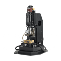
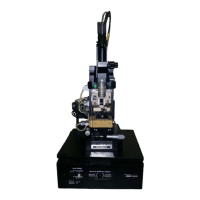
Step-by-step guide for connecting and preparing the AFM hardware.

Aim Laser on End of Cantilever (Adjust Mirror 1)

Find and focus on cantilever

Locate and focus the optical microscope on the cantilever.

Position laser on cantilever

Adjust Mirror 1 to direct the laser onto the cantilever tip.

Aim Laser on Center of Photodetector (Adjust Mirror 2)

Mode, Scanner, and Frequency Selection

Initial Surface Approach

Z-scanner troubleshooting

Solutions for when the Z-scanner fails to detect the surface during approach.

Optimize Scan Parameters

Troubleshooting Poor Image Quality

Additional steps if a good image cannot be obtained, including auto-setup and tip replacement.

Collect Image

Modify with XEI

Flattening your sample

How to flatten AFM images to remove sample tilt or curvature.

Shut Down Procedure

XE-70 AFM Order of Operations

Related product manuals