English
6/8
ICE310-360
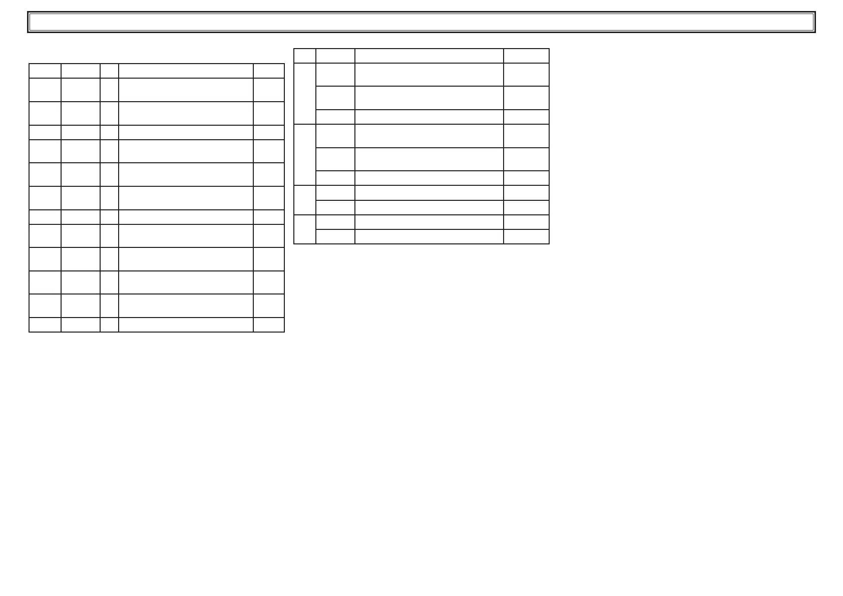
4.6 Alarms management
4.6.1 Digital input alarms
ID CODE LED DESCRIPTION RESET
ID1
HPI
L5
High pressure alarm 1 from pres-
sure switch
M
ID2
LPI
L6
Low pressure alarm 1 from pres-
sure switch
M
ID3
tP
L7 Pump thermal cutout alarm M
ID4
LL
L8
Water tank low water level alarm /
No water ow
A
ID6
PII
L9
Protection alarm compressor 1
/ Phases monitor
M
ID7
PI3
L9
Protection alarm compressor 3
/ Phases monitor
M
ID8
1AC1
- Circuit 1 alarm available M
ID6
HP2
L5
High pressure alarm 2 from pres-
sure switch
M
ID7
LP2
L6
Low pressure alarm 2 from pres-
sure switch
M
ID11
PI2
L9
Protection alarm compressor 2
/ Phases monitor
M
ID12
PI4
L9
Protection alarm compressor 4
/ Phases monitor
M
ID13
1AC2
- Circuit 2 alarm available M
4.6.2 Allarmi da ingressi analogici
AI CODE DESCRIPTION RESET
B1
HAI
Tank water outlet water high tempera-
ture alarm
Warning
LAI
Tank water outlet water low tempera-
ture alarm
A
StI
Sensor open circuit or short circuit M
B2
HA2
Evaporator water outlet water high
temperature alarm
Warning
LA2
Evporator water outlet water low tem-
perature alarm
A
St2
Sensor open circuit or short circuit M
P1
SP1
Transducer open or in short-circuit A
UnL1
UNLOAD Alarm A
P2
SP2
Transducer open or in short-circuit M
UnL2
UNLOAD Alarm A
4.7 Automatic restart
In the event of a power failure, when power is restored the chiller will
assume theOn-Off statusheld at themoment the power was lost.