Bulletin MSG30-3245-INST/UK
Installation Manual
5
Parker Hannifin
Pump & Motor Division Europe
Chemnitz, Germany
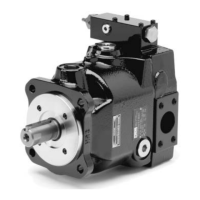
Axial Piston Pump
Series PV, series 44 and higher
Flushing port
The PV pumps of design series 44+ are equipped
with three drain ports*. In addition pumps with seal
option W and P, all pumps PV140 - PV360 and pumps
with X-modification X5830 (bearing flushing port)
are equipped with a flushing port for front bearing
and shaft seal. The flushing flow can - depending on
the actual working conditions - be used to keep the
pump case filled, to warm up the pump (during cold
temperature operation) or for better heat dissipation
e. g. for operation with HFC fluids (water glycole) to
keep the case fluid temperature in the allowed range.
Permanent dead head operation ( >15 min) either for
pumps of frame size 3 and larger (PV063 and higher)
or at high input speeds above 1,800 rpm requires
flushing of the pump case.
Flushing should be taken from the filter/cooling
circuit (e. g. pre-loaded return line). Recommended
flushing flows see following table.
PV016 - PV028 4 - 6 l/min
PV032 - PV046, PV076 5 - 8 l/min
PV063 - PV092 7 - 10 l/min
PV140 - PV180 9 - 12 l/min
PV270 - PV360 13 - 17 l/min
(flushing flow for front bearing: 10 - 15% of the total
flushing flow)
Drive input
For direct drive use elastic coupling free of axial
and radial reaction forces. Please follow strictly the
instructions of the coupling supplier regarding axial
clearance, axial displacement and angular toler-
ances. Couplings never shall be mounted using a
hammer. Threads in the shaft end allow smooth
mounting of the coupling.
The drive shaft should only carry true torque.
Contact Parker for allowable side loads or axial forces.
PV pumps are normally for one direction of rotation
only. Therefore check rotation of drive motor prior to
installation.
Electrical interface
Check voltage, current, phase and connection prop-
erties. Verify direction of motor rotation.
Fluid reservoir
The reservoir needs to meet all system requirements
concerning design, size, location and porting. Beside
beeing reservoir for the hydraulic fluid, the tank also
supports heat dissipation, air removal, water removal
and contamination sedimentation. Often the reservoir
also is the fundament for the motor pump unit. In this
case the separation of pump and remaining struc-
ture by elastic means is mandatory to avoid noise
and vibration being induced into the frame work.
The reservoir needs to be carefully sealed against
ingression of contamination and water. A level indica-
tor and thermometer should be placed in an easily
accessible location.
Fluid content (general rule): stationary systems 3
to 4 times pump nominal flow, 1 times or even smaller
in mobile systems.
Filling of the system
Use only high quality mineral oil based fluids, like
HLP oils according to DIN 51524 part 2. For other
fluids (HFC, HFD, bio degradable or synthetic fluids)
please contact Parker and review the Hydraulic Fluids
Information in Catalogue 2500/UK.
Operation viscosity should be 16 to 100 mm²/s, op-
timum viscosity range is in the 20 to 40 mm²/s, max.
viscosity for short time up to 320 mm²/s.
Because of the possibly uncompatible ingredients
fluids should not be mixed (separation of fluid, reduc-
tion or loss of fluid properties).
Pay highest attention on cleanliness!
Fill system only via a filtration device. Use filtration
unit, when basic contamination of the refill fluid ex-
ceeds class 10 according NAS 1638 (contamination
level 21/19/16 according to ISO 4406). Hydraulic
fluid supplied in barrels typically exceeds these con-
tamination levels.
Filtration
Filtration is the most important factor to the opera-
tional life of the hydraulic system. Statistical analy-
ses indicate, that contamination is by far the most
important reason for system or component failure.
Use return line, pressure and/or bypass filtration.
Bypass filtration usually is most efficient. For general
purpose hydraulic systems with limited requirements
for operational life contamination level 19/15 accord-
ing to ISO 4406 should be desired; corresponding fil-
ter rating: x = 25 µm ( b
25
≥75 ) according to ISO 4572.
Cleanliness level for systems with higher re-quire-
ments for operational life and functional safety should
be 18/16/13 according to ISO 4406; corresponding
filter rating x = 10 µm ( b
10
≥75 ) according to ISO 4572.
Use filter with indicator or electrical signal when
capacity limit is approached.
Suction filter should be avoided. Suction condi-
tions will be affected. Filter can be blocked and cause
cavitation and severe pump damage. When used, a
vacuum sensor with shut off function is mandatory.
Properly dimensioned breather rating ≤10 µm
should be used. Observe min. and max. fluid level;
consider exchange volume with cylinders in the
system.
Filling of pump case
Pump case must be filled via the drain port, to ensure
lubrication, sealing and smooth start up.
 Loading...


