Bulletin MSG30-3245-INST/UK
Installation Manual
9
Parker Hannifin
Pump & Motor Division Europe
Chemnitz, Germany
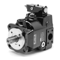
Axial Piston Pump
Series PV, series 44 and higher
The length of the load sensing line can be up to 15
m. If the line is longer than 5 m it has to be consid-
ered, that low environmental temperatures and high
fluid viscosity can have a negative influence to the
compensator performance.
The line should be designed to avoid any significant
pressure drop.
Factory setting for the load sensing pressure differ-
ential is 10 bar ± 1 bar. This adjustment should only
be changed in exceptional cases.
The adjustment is possible by turning the pilot valve
housing after loosening the lock nut.
Please refer to the setting instructions on page 7.
All compensators described in chapters 3 - 6 can
be shipped with a directional control valve for stand-
by operation (compensator codes ends with..W) or
with a proportional pilot valve for electrical pressure
adjustment (compensator code ends with ..K)
Compensator code ...MMW with directional control
valve code D1VW2K*JW for stand-by operation
(24 VDC, normally open)
Compensator code ...MMK with proportional pres-
sure pilto valve code PVACRES-*35
8. Two spool load sensing compensa-
tor, codes ...MTP and ...MTK
interface NG6, DIN24 340 for pilot valve
pressure control stage
load sensing port
flow control stage
The two spool compensator, code ...MT* has two
separate compensator valves for flow (load sensing)
and pressure compensation.
That results in a steeper pressure compensation
curve, which can be beneficial in certain applications.
The flow control stage has no integrated pilot valve,
because this would eliminate the effect of the two
spool control. The pressure stage has no integrated
pilot valve, because during flow control the T port of
the pressure compensator is under control pressure.
This would prevent the pilot valve from opening.
With the adapter kit PVCMCK.. the pressure com-
pensator can be made remote controlled.
On the topside interface any pressure pilot valve can
be mounted. See chapter 3 for requirements.
The factory setting of the flow compensator is
10 ± 1 bar, the adjustment for the pressure com-
pensator is 15 ± 1 bar. These adjustments should
not be modified.
If different adjustments are required by the system or
by the load sensing valves used in the system, see
page 7 for setting instructions.
With ordering code ...MTP a manual adjustable pres-
sure pilot valve code PVAC1PM*S35 is mounted on
the elbow manifold.
With ordering code ...MTK a proportional pilot valve
code PVACRES-*35 is mounted on top. For electronic
pressure control a suitable power amplifier is re-
quired. We recommend the digital modules PCD00...
supplied by Parker HCD.
Because the two spool compensator has no in-
tegrated pilot valves, for a stand-by function the
compensator accessory PVAC1EM*C**35, includ-
ing a directional control valve and a pilot section,
is required.
 Loading...


