Axial Piston Pump
Series PV, series 47 and higher
Bulletin MSG30-3245-INST/UK
Installation manual
5
Parker Hannifin Manufacturing Germany GmbH & Co. KG
Pump & Motor Division Europe
Chemnitz, Germany
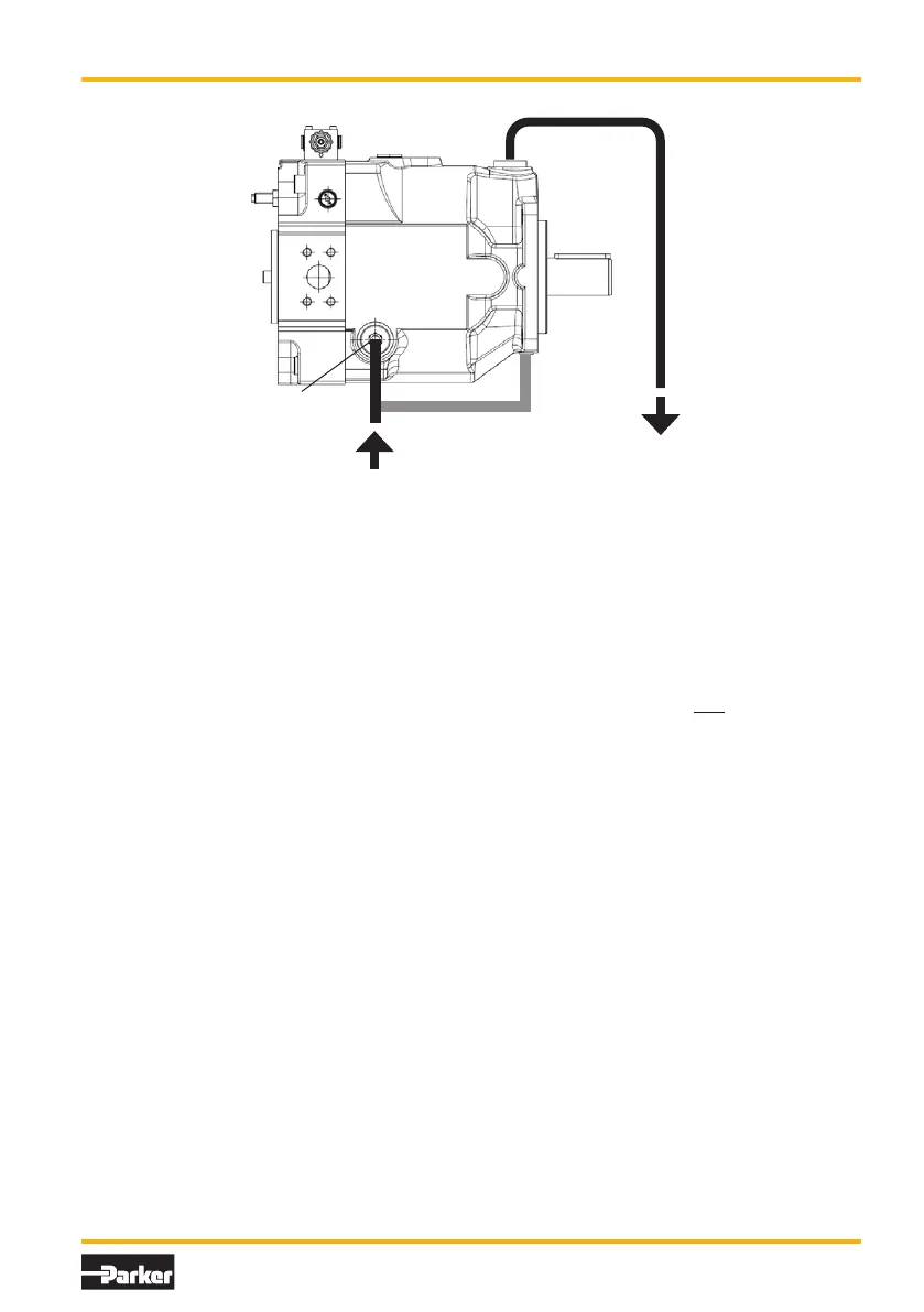
Flushing port
The PV pumps of design series 44+ are equipped
with three drain ports*. In addition all pumps are
equipped with a flushing port for front bearing
and shaft seal. The flushing flow can – depend-
ing on the actual working conditions – be used to
keep the pump case filled, to warm up the pump
(during cold temperature operation) or for better
heat dissipation e.g. for operation with HFC fluids
(water glycole) to keep the case fluid tempera-
ture in the allowed range. Permanent dead head
operation ( >15 min) either for pumps of frame
size 3 and larger (PV063 and higher) or at high
input speeds above 1,800 rpm requires flushing
of the pump case.
Flushing should be taken from the filter/cooling
circuit (e.g. pre-loaded return line). Recom-
mended flushing flows see following table.
PV016 – PV028 4 – 6 l/min
PV032 – PV046 5 – 8 l/min
PV063 – PV092 7 – 10 l/min
PV140 – PV180 9 – 12 l/min
PV270 – PV360 13 – 17 l/min
(flushing flow for front bearing: 10 – 15 % of the
total flushing flow)
Drive input
For direct drive use elastic coupling free of axial
and radial reaction forces. Please follow strictly
the instructions of the coupling supplier regarding
axial clearance, axial displacement and angular
tolerances. Couplings never shall be mounted
using a hammer. Threads in the shaft end allow
smooth mounting of the coupling.
The drive shaft should only carry true torque.
Contact Parker for allowable side loads or axial
forces.
PV pumps are normally for one direction of rota-
tion only. Therefore check rotation of drive motor
prior to installation.
Electrical interface
Check voltage, current, phase and connection
properties. Verify direction of motor rotation.
Fluid reservoir
The reservoir needs to meet all system require-
ments concerning design, size, location and
porting. Beside beeing reservoir for the hydraulic
fluid, the tank also supports heat dissipation,
air removal, water removal and contamination
sedimentation. Often the reservoir also is the
fundament for the motor pump unit. In this case
the separation of pump and remaining structure
by elastic means is mandatory to avoid noise and
vibration being induced into the frame work. The
reservoir needs to be carefully sealed against
ingression of contamination and water. A level
indicator and thermometer should be placed in
an easily accessible location.
Q
leak
Q
flush
L1
L4
L2/L3

 Loading...


