Axial Piston Pump
Series PV, series 47 and higher
Bulletin MSG30-3245-INST/UK
Installation manual
7
Parker Hannifin Manufacturing Germany GmbH & Co. KG
Pump & Motor Division Europe
Chemnitz, Germany
The adjustment of the compensating pressure is
performed for the standard pressure com pen sa-
tor directly at the compensator.
To adjust the pressure, the lock nut (SW 13) is to
be loosened and the adjustment spindle is to be
turned (screw driver).
Turning clockwise will increase the compensat-
ing pressure, turning counter-clockwise will
decrease the compensating pressure.
The compensating pressure can be adjusted in a
range from 15 to 350 bar (approx. 125 bar/turn).
By turning the pressure pilot cartridge housing
the compensator dierential can be adjusted.
It is factory set to 15±1 bar and should not be
changed (approx. 20 bar/turn).
Dierent compensator dierential settings can
cause instability or excessive power losses.
By using adapter kit PVCMCK** (below 47de-
sign) / PVCCK** (since 47 design) the standard
Size
Displacement
change per mm
(approx. cm³/U)
Displacement
change per turn
(approx. cm³/U)
Minimum
adjustable
displacement
(approx. cm³/U)
P V 016 1.5 1.5 9
PV020 1.5 1.5 13
PV023 1.5 1.5 16
PV028 1.5 1.5 20
PV032 2.2 2.2 17
PV040 2.2 2.2 25
PV046 2.2 2.2 30
PV063 3.4 5.1 35
PV080 3.4 5.1 50
PV092 3.4 5.1 65
PV140 5.6 8.4 20
PV180 5.6 8.4 60
PV270 6.8 10.2 120
PV360 8.6 12.9 180
pressure compensator can be made remote
controllable. This adapter replaces one of the side
plugs. Adapters are available for G1/4, M14x1.5
ISO 6149-1 and 7/16-20 UNF.
See also the remarks in chapter 6.
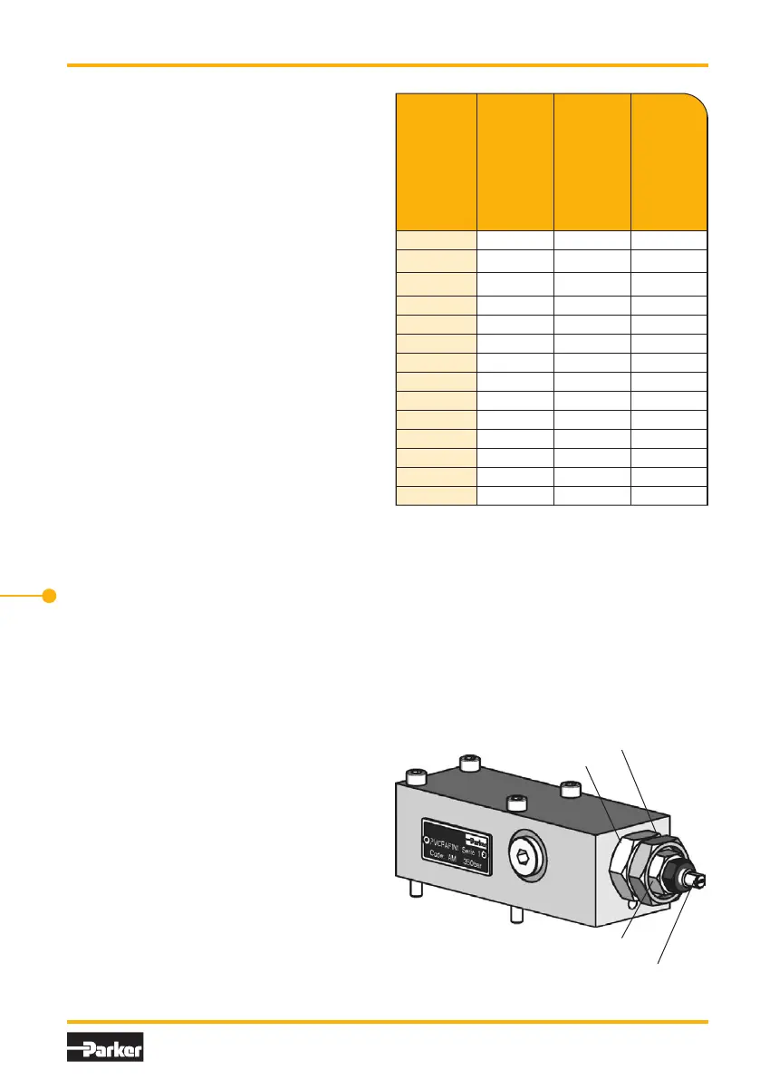
3. Standard pressure compensator, code ...MMC
compensator dierential adjustment
pressure adjustment
lock nut
lock nut
Adjustment should only be made with the pump
working at full displacement (not compensated)
and at a low output. At full displacement the piston
area of the servo piston is under case pressure.
Opening the self-sealing nut will only cause a
negligible leakage under these conditions.
Turning the adjustment screw clockwise will re-
duce the pumps displacement. The table shows
the displacement change per mm resp. per turn
and the minimum adjustable displacement.
Note: All pumps are adjusted and tested after
assembly in our factory. Only the compensator
pressure needs to be adjusted. That is done on
the pilot valve spindle. No other adjustments on
the compensator or the pump is required. Only
after service or repair a basic adjustment needs
to be performed.

 Loading...


