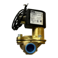
DESCRIPTION
These valves are 2-way, pilot operated models requiring a
minimum operating pressure differential to insure valve
operation. They are available in normally closed (N.C.)
versions and are offered in a combination of brass and
stainless steel construction. Valves may be ordered with
either NEMA 2, 4, 4X integrated coils for ordinary locations or
NEMA 4, 4X, 7. and 9 for hazardous locations: Divisions I
and II; Class I, Groups A, B, C, and D; Class II, Groups E, F,
and G. Additional solenoid coils and enclosures are offered
as described in our catalog.
PRINCIPLES OF OPERATION
The inlet port of the 73218 valves is stamped "P" on the valve
body. The outlet port is not marked.
Normally closed type: 73218
De-energized: Pressure is connected to the inlet port. Flow
through the valve is prevented by a plunger closing off the
diaphragm pilot orifice and a diaphragm sealing against the
main orifice.
Energized: The plunger is lifted off the pilot orifice and vents
the pressure behind the diaphragm. The venting creates a
pressure imbalance across the diaphragm, which causes the
diaphragm to open the main orifice allowing flow through the
valve.
CAUTION: A minimum operating pressure differential of 5 psi
is required for proper valve operation.
FLUID CODES
Listed below are the codes utilized by Underwriters
Laboratories (UL) and the Canadian Standards Association
(CSA) for various common fluids. The codes for those fluids
that are approved or certified by the agencies for use with
each valve are printed on the outside of the individual
packaging.
CODE
FLUID
A - Air or nontoxic, nonflammable gases
Ac - Acetylene
F - Common refrigerants except ammonia
G - City gas supplied by public utilities
Ga - Gasoline
HO - Petroleum based hydraulic oils having viscosities
of 125 to 400 SSU at 100° F (38°C)
02 - Nos. 1 and 2 fuel oils, oils having viscosities not
more than 40 SSU at 100° F (38°C)
02 - 06 - No. 2 through No. 6 oil
Ox - Oxygen
S
-
Steam
W -
Water or other aqueous nonflammable
liquids for the maximum fluid temperatures, as well as
valve ambient limitations, check the valve part number on
the nameplate and refer to the catalog or the outside of
the shipping package.
INSTALLATION INSTRUCTIONS
Mounting position and pressure limits: Valves can be
mounted directly on piping. Mounting brackets are
available and may be ordered separately.
The 73218 valves are designed to be multi-poised and so
will perform properly when mounted in any position.
However, for optimum life and performance the valves
should be mounted vertically upright so as to minimize
wear and reduce the possibility of foreign matter accumulating
inside the sleeve area.
Line pressure must conform to nameplate rating.
Piping: Remove protective closures from the ports. Connect
line pressure to the inlet port. Use of Teflon tape, thread
compound or sealants is permissible, but should be applied
sparingly to male pipe threads only
.
CAUTION: Do not allow foreign particles, Teflon tape, or
thread compound to enter valve. Tightening torque should not
exceed the following values for each port size:
Only wrench flats provided on the body should be used when
applying torque. Do not use sleeve or enclosure as a lever.
Media filtration: Normally filtration is not required, but dirt or
foreign material in the media may cause excessive leakage,
wear, or in exceptional cases, malfunction. If filtration is used,
install the filter on the inlet side as close to the valve as
possible. Clean periodically depending on service conditions.
Lubrication
:
Lubrication is not required although airline
lubrication will substantially increase valve life.
CAUTION
: Valves which have seals or other components
made from ethylene propylene rubber must not be exposed
to petroleum based lubricants or other hydrocarbons.
Electrical
connection
:
Electrical supply must conform to
nameplate rating. Connect coil leads or terminals to the
electrical circuit using standard electrical practices in
compliance with local authorities and the National Electrical
Code.
WARNING:
Valves to be installed in Hazardous Locations,
must be outfitted with Hazardous Location coils only. Verify
nameplate data and coil part number before installing the
valve
 Loading...