WARNING; Turn off electrical power before connecting the
valve to the power source.
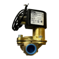
If the coil assembly is located in an inconvenient orientation, it
may be reoriented to facilitate installation. Loosen coil
assembly nut, rotate coil assembly to desired position, then
retighten the nut with an input torque of 43-53 in-lbs.
DI
N Coil and Terminal Box Assembly (Coil / Option Codes
D1DB, D2DB, D3DB): Loosen cover screws and swing cover
90° toward the conduit hub in order to access the interior
space. Separate the plastic block containing the screw
terminals from the metal enclosure using a small flat head
screwdriver. Feed the lead wires through the conduit hub and
attach them to the appropriate screw terminal. For electrical
connection within the terminal box, use field wire that is rated
90° C or greater. Snap the plastic block back into place
inside the metal enclosure. Replace the cover and hand-
t
ighten the cover screws. Place the gasket over the DIN
spades on the coil and press the terminal box and coil
together. Secure the terminal box to the coil using the
mounting screw provided. Apply 20 to 30 in-lbs. torque to the
mounting screw.
S
crew Terminal Coil and Terminal Box Assembly (Coil
/Option Codes S1TB, S2TB, S3TB): Loosen cover
screws and swing cover 90°C toward the conduit boss in order
to access the interior space. Feed the lead wires through the
conduit hub and attach them to the appropriate screw
terminal. For electrical connection within the terminal box,
use field wire that is rated 90°C or greater. Replace the
cover and hand-tighten the cover screws. Press the terminal
box and coil together. Secure the terminal box to the coil
using the mounting screw provided. Apply 20 to 30 in-lbs.
torque to the mounting screw.
CAUTION: When the DIN or Screw Terminal coils are used
with the Terminal Box Assembly, be sure to apply a wrench to
the wrench flats on the conduit hub when installing electrical
conduit.
Coil/enclosure temperature: Standard valves are supplied
with coils designed for continuous duty service. Normal free
space must be provided for proper ventilation. When the coil is
energized continuously for long periods of time, the coil
assembly will become hot. The coil is designed to operate
permanently under these conditions. Any excessive heating
will be indicated by smoking and/or odor of burning coil
insulation.
For the maximum valve ambient conditions, as well as the
fluid temperatures, check the valve part number on the
nameplate and refer to the catalog or the outside of the
shipping package.
MAINTENAIICE
Note: Depending on service conditions, fluid being used,
filtration, and lubrication, it may be required to periodically
clean and/or replace worn components. See Disassembly
Instructions.
CAUTION: Do not expose plastic or elastomeric materials to
any type of commercial cleaning fluid. Parts should be cleaned
with a mild soap and water solution.
DISASSEMBLY INSTRUCTIONS
WARNING: Depressurize system and turn off electrical
power to the valve before attempting repair.
The valves need not be removed from the line. To remove
the coil assembly:
Normally Closed Valves - For both ordinary and hazardous
location constructions, unscrew the nut on the top of the coil
assembly. The wave washer and coil assembly can now be
removed.
To disassemble the pressure vessel:
CAUTION: If the sleeve assembly does not have a hex style
flange, do not use a pipe wrench directly on the sleeve.
Instead, use a Skinner U99-011 wrench nut to remove the
sleeve assembly.
Normally Closed Valves - Slide the Skinner U99-011 wrench
nut over the sleeve tube. To unscrew the sleeve assembly,
mate the wrench nut to the sleeve flange and turn the wrench
nut. The plunger, return spring, and flange seal may now be
removed.
Unscrew the cover screws. If the cover cannot be easily lifted
off the body, laterally tap the cover or gently pry the cover
from the body with a screwdriver. Care must be taken not to
damage the diaphragm, cover, or body. Diaphragm return
spring(s), diaphragm assembly, and O-rings can now be
removed.
Replacement Parts: When ordering replacement parts kits,
specify valve number and voltage from nameplate. Parts kits
are available for each valve. Parts included in each kit are
marked with an asterisk (*). See exploded views.
REASSEMBLY INSTRUCTIONS
To reassemble the pressure vessel:
WARNING: When replacing coils, valves equipped with
Hazardous. Location coils must use Hazardous Location
replacement coils only. Verify nameplate data and coil part
number before installing the replacement coil.
Refer to exploded view drawings. Parts must be replaced in
the order shown.
Install the diaphragm assembly into the body. For 3/8" through
1-1/4" NPT ported valves, make sure that the diaphragm tab is
located over the outlet port of the body. For 1-1/2" NPT ported
valves, the diaphragm tab must be located 30 degrees
counter-clockwise from the outlet port when viewed from the
diaphragm side.
The diaphragm bolt holes and flow holes must line up with the
appropriate bolt and flow holes in the valve body. Tighten the
cover screws with an input torque of 65-85 in-lbs. for the 3/8"
through 3/4" NPT port sizes, and 110-150 in-lbs. for the 1"
through 1-1/2" NPT port size valves.
Install the plunger and spring in the sleeve. Tighten sleeve
assembly with an input torque of 130-150 in-lbs.
With coil assembly repositioned on the sleeve, slide the wave
washer over the sleeve and tighten coil assembly nut with an
input torque of 43-53 in-lbs.
Refer to the Installation Instructions for remaining installation
procedures.
 Loading...


