Description
4
2 Description
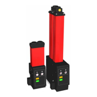
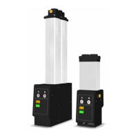
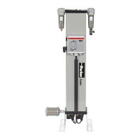
Parker domnick hunter desiccant dryers are designed to remove moisture vapour from compressed air. Providing pressure dewpoints of
-40°C (-40°F) or -70°C (-100°F) at specified conditions.
The dryers comprise of extruded aluminium columns. Each column contains twin chambers filled with desiccant material that dries the
compressed air as it passes through. One chamber is operational (drying), whilst the opposite chamber is regenerating by Pressure Swing
Adsorption (PSA).
Pressure Swing Adsorption (PSA)
A small amount of the dried compressed air is used to regenerate the spent desiccant bed. Dried air at line pressure is expanded to atmospheric
pressure through the regenerating column.
Dewpoint Dependent Switching (DDS)
If DDS is fitted, this will adjust the dryer's cycle in line with the moisture loading placed upon it, by constantly monitoring the processed air
moisture content. Also available as a retrofit to all dryer models.
2.1 Technical Specification
This specification is valid when the equipment is located, installed, operated, and maintained as specified within this user guide.
Stated flows are for operation at 7 bar g (102 psi g) with reference to 20ºC (68ºF), 1 bar (a) (14.5 psi), 0% relative humidity. For flows at other
conditions, apply the correction factors shown.
Correction Factors
Minimum Drying Capacity = Inlet Flow Requirement x CFT x CFP
Temperature Correction Factor (CFT)
Pressure Correction Factor (CFP)
Model Pipe Size
m
3
/min m
3
/hr
cfm
DME012 3/4” 0.68 40.8 24
DME015 3/4” 0.91 54.6 32
DME020 3/4” 1.19 71.4 42
DME025 3/4” 1.5 90 53
DME030 3/4” 1.84 110.4 65
DME040 3/4” 2.49 149 88
DME050 1” 3 180 106
DME060 1” 3.68 220.8 130
DME080 1” 4.98 298.8 176
Max Inlet
Temperature
o
C
25 30 35 40 45 50
o
F
77 86 95 104 113 122
CFT 1.00 1.00 1.00 1.03 1.14 1.37
Min Inlet
Pressure
bar g 4 5 6 7 8 9 10 11 12 13 14 15 16
psi g 58 73 87 102 116 131 145 160 174 189 203 218 232
CFP 1.59 1.33 1.14 1.00 0.88 0.80 0.72 0.67 0.61 0.57 0.53 0.50 0.47
 Loading...