!
SERIES
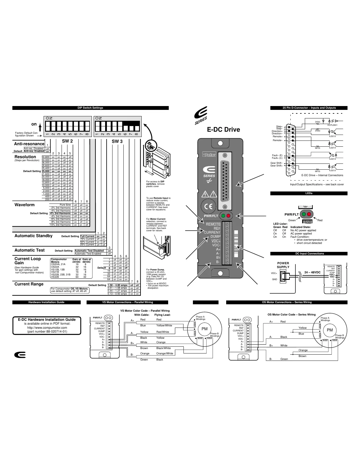
E-DC Drive
VS Motor Connections – Parallel Wiring Hardware Installation Guide OS Motor Connections – Series Wiring
DIP Switch Settings
SERIES
25 Pin D-Connector – Inputs and Outputs
LEDs
DC Input Connections
LED
reen Red Indicated State:
ff Off No AC power applied
n On Fault Condition:
• drive overtemperature; or
• short circuit detected
24 – 48VDC
E-DC Hardware Installation Guide
is available online in PDF format:
http://www.compumotor.com
(part number 88-020714-01)
RedGreen
PWR/FLT
VD
POWER
SUPPLY
REMOTE
REF
CURRENT
DUMP
VDC+
VDC-
A+
A-
B+
B-
PM
Phase A
Windings
Phase B
Windings
Red
Blue
Black
Yellow
White
Orange
Green
A+
A-
B+
B-
Brown
Red
Yellow/White
Yellow
Red/White
Orange
Orange/White
Black
Black/White
REMOTE
REF
CURRENT
DUMP
VDC+
VDC-
A+
A-
B+
B-
PWR/FLT
VS Motor Color Code – Parallel Wiring
Flying Lead:With Cable:
PM
Phase A
Windings
Phase B
Windings
Red
Blue
Black
Yellow
White
Brown
Green
A+
A-
B+
B-
Orange
REMOTE
REF
CURRENT
DUMP
VDC+
VDC-
A+
A-
B+
B-
PWR/FLT
OS Motor Color Code – Series Wiring
on
off
3
off
45
7
6
1
8
2
Anti-resonance
Automatic Test
Current Loop
Gain
(See Hardware Guide
for gain settings with
non-Compumotor motors)
Current Range
Anti-res. Disabled
Anti-res. Enabled
on
on offon on
off onon on
off offon on
on onon off
on offon off
on onon on
off onon off
off offon off
on onoff on
on offoff on
off onoff on
off offoff on
on onoff off
on offoff off
off onoff off
off offoff off
1
23
on
1
2
3
4
5
6
7
8
Automatic Test Disabled
Automatic Test Enabled
Waveform
on
on
off
off
on
off
on
off
Automatic Standby
Full Current
75% Current
50% Current
25% Current
Default Setting
Default Setting
on
off
off
on
off
on
on
off
off
on
off
on
off
on
off
on
off
off
off
off
on
on
on
on
Pure Sine
-2% 3rd Harmonic
-4% 3rd Harmonic
-4% 3rd Harmonic
-4% 3rd Harmonic
-6% 3rd Harmonic
-8% 3rd Harmonic
-10% 3rd Harmonic
50,800
50,000
36,000
25,600
25,400
25,000
21,600
20,000
18,000
12,800
10,000
5,000
2,000
1,000
400
200
Default Setting
Default Setting
Default
5
46
7
8
off
off
off
off
on
on
on
on
off
off
on
on
off
off
on
on
off
on
off
on
off
on
off
on
1
2
4
8
16
32
64
64
SW 2
SW 3
1
2
3
4
5
6
7
8
O
N
O
N
Resolution
(Steps per Revolution)
off
off
on
on
off
on
off
on
1.58 – 4.80 amps
0.51 – 1.58 amps
0.44 – 1.27 amps
0.13 – 0.50 amps
Default Setting
Factory Default Con-
figuration Shown
Default
For Motor
connect a
resistor between
cover for values.
For Power Dum
dissipation
To use Remote Inpu
uations.
For access to DIP
switches
remove
plastic cover
Compumotor Gain at Gain at
Motors 24VDC 48VDC
OS2HA, 21A 16 8
OS22A 32 16
VS12B, 13B 32 16
VS21B 16 8
VS22B, 23B, 31B 32 16
VS32B 64 32
For Compumotor OS, VS Motors,
use default setting: #7 off, #8 off.
1
2
3
4
5
6
7
8
O
N
1
2
3
4
5
6
7
8
O
N
R
E
M
O
T
E
R
E
F
C
U
R
R
E
N
T
D
U
M
P
V
D
C
+
V
D
C
-
A
+
A
-
B
+
B
-
P
W
R
/F
L
T
!
S
E
R
I
E
S
1
2
3
4
5
6
7
8
9
10
11
12
13
14
15
16
17
18
19
20
21
22
23
24
25
E-DC Drive – Internal Connections
Input/Output Specifications – see back cover
ILD213
ILD213
ILD213
ILD213
HCPL2631
243Ω
243Ω
681Ω
681Ω
Remote–
Remote+
Fault+
–
Step–
Step+
Direction–
Direction+
All manuals and user guides at all-guides.com

 Loading...