3
Bulletin MSG30-8302-INST
Marketing information
Parker Hannifin
Pump & Motor Division Europe
Trollhättan, Sweden
Fixed and Variable Motors
Series F11/F12 and V12/V14/T12
INSTALLATION PROCEDURE
CONNECTION
Sensor wires are susceptible to radiated noise.
Therefore, the following shoud be noted:
• Uninterrupted screened 4 wire cable must be
used and the screen only connected to the
appropriate instrument screen input terminal or
0V. Connections to power earth are not
advisable.
• The sensor wires must be installed as far away
as possible from electrical machines and must
not run in parallel with power cables in the
vicinity.
The maximum cable length that can be utilized is de-
pendent on sensor voltage, how the cable is installed,
and cable capacitance and inductance. It is, however,
always advantageous to keep the distance as short as
possible. The sensor cable supplied can be length-
ened via a terminal box located in an IP20 protected
connection area (per DIN 40050).
Contact Pump & Motor Divsion Europe for
recommendations.
Connections and Pulse Diagram:
Direction of rotation
Speed sensor intallation, F12, V12,V14, T12
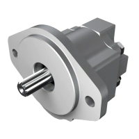
INSTALLATION INFORMATION
As the sensor has a built-in differential Hall effect
device, the sensor housing must be aligned according
to the drawing (Fig. 1& 2) of the Speed Sensor Instal-
lation picture. If it is not, the sensor may not function
properly and noise immunity decreases. The sensor
is non-sensitive to oil and the stainless steel housing
withstands hazardous environment conditions.
- Install the sensor in the threaded hole (M12x1) of
the F12/V12/V14/T12 bearing housing; turn the
sensor until its head just touches the ring gear
teeth (F12) or the shaft head (F12-250/V12/V14/
T12); refer to the installation drawing above.
- On *F11 the pistons positions must be known
before mounting the sensor. Install the sensor in
the threaded hole (M12x1) of the F11 barrel hous-
ing; turn the sensor until its head just touches the
piston.
- When mounting the sensor in the threaded hole be
sure that you also rotate the cable so the cable not
get twisted.
- Back off the sensor one turn (counter clockwise).
- If required, back it off further until the sensor
guiding hole centerline is as shown in Fig. 1 & 2 or
180° opposite.
- Tighten the seal nut; max 12 Nm (100 lb in). Be
sure that the position of the guiding hole centerline
still is correct.
- Connect the electrical wires as shown in the
schematic. Please note the instructions on
page 1 regarding screening.
- If you only use one signal, we recommend you to
use S2 cable. Cut S1 cable and isolate.
* F11: -6, -10, -12. -14, -19
Fig. 1
Fig. 2
Depressions
(V12/V14 shaft head)
Ring gear
(F10, F 12)
0.1-2
50 [1.97]
63.4 [2.50]
Bearing
housing
Seal
nut
[0.004-0.78]
Rotation
RED - VDC
WHITE - S1
BLACK - S2
BLUE - GND
OUT I
OUT II
Rotation
RED - VDC
WHITE - S1
BLACK - S2
BLUE - GND
OUT I
OUT II
Sensor guiding hole
Sensor guiding
hole

 Loading...