The provided document is a service procedure manual for the Parker 700 Series Low Speed High Torque (LSHT) hydraulic motor, specifically Bulletin SM1531-001/US, effective May 2006. This manual outlines the steps for disassembly, inspection, and assembly of the motor, along with troubleshooting and maintenance guidelines.
Function Description
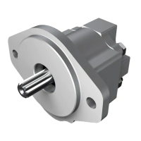
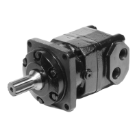
The Parker 700 Series LSHT hydraulic motor is designed to provide long life while operating with low radial side loads. It converts hydraulic power into mechanical rotational energy, delivering high torque at low speeds. The manual details the internal components and their arrangement, which facilitate this function. Key components include the internal shaft, commutator plate, IGR™ sets (front and rear), center block, output shaft, and various seals and bearings. The motor can also be equipped with an optional solenoid for pilot operation, allowing for changes between normally parallel and normally series operation.
Important Technical Specifications
While the manual does not provide a comprehensive list of all technical specifications, it does mention several important parameters and components:
- Displacement: The service parts list includes various motor displacements, such as 12.9/25.8, 10.6/21.2, 8.8/17.6, 7.1/14.2, 5.4/10.8, and 3.6/7.2, indicating a range of available motor sizes.
- Shaft Options: The motor supports both 1" and 1.25" diameter output shafts, with different configurations like keyed, spline (6B, 13T, 14T), and tapered shafts. A significant change noted is that starting April 1, 1996 (date code 092-96), all 700 Series motors use 1.25" diameter type "A" and "B" flanges and a common seal kit, with 1" diameter flanges no longer available for replacement shafts.
- Seal Kits: Specific seal kits are identified: SK000202 for 1" type shafts prior to 092-96, and SK000203 for all other type 700 series motors. These kits include body O-rings, flange O-rings, dust seals, high-pressure seals, solenoid block O-rings, and thrust bearings.
- Torque Specifications: Critical torque values are provided for assembly:
- Cover bolts (Item 1): Initial torque of 15 ft. lbs., increasing diagonally to 28 ft. lbs.
- Front bearing housing bolts (Item 15): Initial torque of 15 ft. lbs., increasing diagonally to 30 ft. lbs.
- Flange cap screws (Item 10): 25 ft. lbs.
- Solenoid block bolts (Item 25): 15 ft. lbs.
- Fluid and Temperature:
- Maximum operating temperature: 180°F (82.2°C). Exceeding this can cause seals to shrink, harden, or crack.
- Minimum fluid viscosity at maximum temperature: 50 SSU.
- Recommended filtration: Beta 25 ratio of at least 2.
Usage Features
The 700 Series motor is designed for applications requiring low speed and high torque. The manual emphasizes the importance of proper hydraulic system conditions for optimal performance and longevity.
- Pilot Operation: The motor can be configured for either normally parallel or normally series pilot operation by reversing the spool direction within the solenoid block. This flexibility allows adaptation to different control system requirements.
- Radial Load Limits: Users are advised to refer to the catalog for specific radial load limits, indicating that while designed for low radial side loads, there are defined operational boundaries.
Maintenance Features
The manual provides comprehensive instructions for maintaining the 700 Series motor, focusing on proper procedures and safety.
- Troubleshooting Guide: A detailed checklist helps identify common issues like oil leakage, significant loss of speed under load, low mechanical efficiency, and lack of pressure. It distinguishes between hydraulic system problems (e.g., temperature, fluid viscosity, filtration) and motor component issues.
- Preparation for Service: Emphasizes working in a clean, well-lighted environment, having proper tools and materials, and using clean, petroleum-based solvent. It also stresses the importance of plugging open ports and cleaning the motor exterior before disassembly.
- Disassembly and Inspection:
- Cleaning: All parts (except seals) should be cleaned in petroleum-based solvent and blown dry.
- Seal Replacement: All seals and seal rings must be discarded and replaced with new ones during reassembly.
- Part Inspection: The shaft should be inspected for scratches, pitting, or galling. Minor scratches can be polished with fine emery paper, but deep scratches or pitting necessitate shaft replacement. Other components should also be checked for contamination or damage.
- Thru Shaft Option: If a motor has a thru shaft option and the seals are leaking, the entire cover must be replaced as it contains no serviceable parts.
- Assembly:
- Lubrication: All seals, rollers, and threaded bolt ends should be lightly oiled prior to assembly.
- Seal Installation: Specific instructions are given for installing dust seals and shaft seals, noting the correct orientation (flat edge facing into the flange for dust seal, flat side facing out for shaft seal).
- Thrust Bearing: For 1" diameter shafts, the thrust bearing must be pressed into the flange with the copper side facing inward. For 1.25" diameter shafts, the thrust bearing grooves must face towards the shaft seal.
- Timing: Proper timing of the motor during assembly is crucial for smooth low-speed operation, achieved by aligning the valve plate window perpendicular to the flat center block port face.
- Check Balls and Rollers: Assembly grease can be used to hold check balls in place. Rollers and rolls have distinct shapes (square ends for rolls, radius ends for rollers) and must be installed correctly.
- Final Checks: After assembly, the motor should be pressurized with 100 psi dry air or nitrogen and submerged in solvent to check for external leaks. Operational checks on a test stand are also recommended.
- Maintenance Tips:
- Adjust fluid level in the reservoir.
- Report malfunctions or accidents.
- Do not weld, braze, solder, or alter motor components.
- Do not cold straighten or bend parts.
- Prevent dirt from entering the hydraulic system.
- Investigate and correct external leaks.
- Comply with filter replacement specifications.
- Avoid striking or dropping the motor on the shaft end.
- Do not force couplings onto the shaft.
The manual emphasizes safety warnings regarding flammable solvents and the necessity of eye protection and compliance with air pressure requirements. It also warns against mixing oil types and using non-approved oils, which can deteriorate seals.