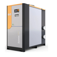
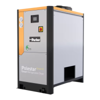
This document describes the Parker KE-MT 120-600 adsorption dryer, an industrial device designed for drying compressed air. The dryer operates by removing humidity from compressed air through an adsorption process, making it suitable for various industrial applications.
Function Description
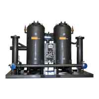
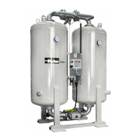
The KE-MT 120-600 adsorption dryer utilizes two vessels, each filled with a porous drying agent, to remove moisture from compressed air. The process involves alternating between adsorption and regeneration phases in these vessels.
Adsorption: Humid compressed air from a compressor enters the dryer and flows upwards through one of the pressurized absorption vessels. The drying agent in this vessel dehumidifies the air, which is then supplied as dry compressed air to the pipe network.
Regeneration: Simultaneously, while one vessel is adsorbing, the other undergoes regeneration to prepare it for a renewed take-up of humidity. Regeneration is divided into three phases:
- Expansion Phase: The pressure in the regenerating chamber is released to ambient pressure via a muffler within seconds. This process is characterized by a sudden, powerful flow noise from the muffler.
- Dehumidification Phase: A portion of the dried compressed air is bled through an orifice plate and fed through the depressurized chamber. This air flow picks up the humidity stored in the drying agent and expels it into the atmosphere through the muffler.
- Pressure Build-up Phase: After dehumidification, the pressure in the regenerated vessel is gradually built up to the operating pressure. This allows for a smooth switchover from regeneration to adsorption at the operating pressure level.
With the optional dewpoint-sensing control, a Standby Phase follows regeneration. In this phase, the fully regenerated vessel is ready for absorption and will switch into operation as soon as the measured dewpoint at the compressed air outlet reaches a preset value.
Switchover: When the drying agent in the adsorbing chamber becomes saturated with humidity, a switchover between the vessels occurs. The previously regenerating vessel begins adsorption, and the previously adsorbing vessel begins regeneration, repeating the cycle.
Important Technical Specifications
The KE-MT 120-600 series offers various models with different capacities and dimensions.
Operating Range:
- Fluid group: 2
- Max. operating pressure: 10 bar
- Min. operating pressure: 6 bar
- Min. ambient temperature: ≥+1°C (33.8°F)
- Max. ambient temperature: ≤+50°C (122°F)
- Noise level: +3 dB (A) relative to free field measurement, 1 m surrounding field (105-120 dB(A))
- Mains voltage: (see type plate)
- Protection class: IP 65
Performance Details (KE-MT 120 to KE-MT 600 models):
- Capacity*: Ranging from 1200 m³/h (KE-MT 120) to 6100 m³/h (KE-MT 600).
* relative to 1 bar (abs.) and 20 °C (68 °F) at 7 bar operating pressure and a feed temperature of 35 °C (95 °F).
- Dimensions (Length x Height x Width):
- KE-MT 120: 1060 mm x 2080 mm x 840 mm
- KE-MT 600: 2160 mm x 2820 mm x 1565 mm
- Weight: Ranging from 640 kg (KE-MT 120) to 2850 kg (KE-MT 600).
- Connection (Inlet/Outlet): Ranging from DN 50 (KE-MT 120) to DN 125 (KE-MT 600).
Usage Features
The dryer is designed for industrial use and requires specific installation and operating conditions.
Installation Requirements:
- Must be installed within a building, protected from moisture.
- Ambient temperature should not drop below +1.5 °C (34.7 °F).
- Installation area must be level, firm, vibration-proof, and capable of supporting the dryer's weight.
- Sufficient spacing (minimum 1 m) around the top, sides, and rear is required for maintenance and drying agent changes.
- The dryer should be transported and stored in an upright position to prevent mixing of desiccant layers.
- Properly anchored to the floor using pre-drilled bores.
- Compressed air inlet and outlet lines, along with shut-off valves, must be installed by the owner.
- All piping must be stress-free and have correct diameters.
- Electrical connections must be made by authorized personnel, ensuring proper cross-section of the supply cable and voltage.
Control and Monitoring:
- ON/OFF Switch: Located on the side of the switchbox, it controls power supply and operating mode (fixed cycle or variable cycle with optional compressor synchronization/dewpoint-sensing control).
- Display Panel: Equipped with LEDs and a digital display.
- LED Power (1): Indicates when the dryer is switched on.
- Flow Diagram (2): Four LEDs show the current operating phases (Adsorption B1/B2, Regeneration 1/2).
- Digital Display (3): Shows individual program steps and remaining time in seconds. Also displays "SEr." for service due, and dewpoint values/error messages with optional dewpoint-sensing control.
- Vessel Pressure Gauge: Displays operating overpressure, indicating the phase of each vessel. During regeneration, pressure should decrease to 0 bar in the dehumidification phase. Dam pressure (residual pressure above 0 bar during regeneration) should not exceed 0.3 bar.
- Compressor Synchronization (Optional): Allows the dryer's regeneration to synchronize with compressor operation, stopping regeneration when the compressor stops and restarting when it restarts.
- Dewpoint-Sensing Control (Optional): Enables variable cycle operation based on measured dewpoint. The system switches vessels when the dewpoint at the compressed air outlet reaches a preset value.
- Signaling Contacts (Optional): Allows monitoring of dryer operation and dewpoint alarms from an external device.
Safety Notes:
- Only authorized and qualified personnel should operate and maintain the dryer.
- Always wear eye and ear protection when working near the dryer due to sudden air ejection during depressurization.
- Never remove parts or manipulate the dryer while it is pressurized. Depressurize the plant before any work.
- Beware of crushing risk at the universal shaft and drives during switching.
- Electrical supply and external power lines are live even when switched off; make them voltage-free before working on the electrical system.
- Do not misuse the dryer as a climbing aid.
- Handle drying agents with care; wear a dust mask and eye protection during filling/emptying to avoid dust generation and skid risk from spills.
- Do not operate a damaged dryer.
- Do not make unauthorized conversions or modifications.
Maintenance Features
Regular maintenance is crucial for the dryer's efficient and safe operation.
Daily Maintenance Tasks:
- Visual and Function Check: Inspect for external damage or unusual noise. Eliminate defects.
- Clean Dryer: Remove loose dust with a dry cloth; clean surfaces with a moist, well-wrung cloth.
- Check Dam Pressure: Ensure pressure gauges indicate 0 bar after depressurization. If dam pressure exceeds 0.3 bar, depressurize and shut down the dryer, then check for blocked mufflers, contaminated dust sieves, or old drying agent.
Maintenance Work to be Completed Every 12 Months:
- Renew Filter Element of Control Air Filter: Inspect and replace annually to ensure proper valve actuator function.
- Renew Mufflers: Replace every 12 months and after each desiccant change to prevent dangerous overpressure and bursting.
- Renew Dewpoint Sensor (Optional): Recommended annually for precision dewpoint measurement.
- Replacing Pilot Valves: Part of every service kit, replace every 12 months.
Maintenance Work to be Completed Every 48 Months:
- Pressure Vessel Inspection: May be prescribed by national regulations. Requires removal of drying agent.
- Check Fittings: Inspect sieve bottoms, dust sieves, and gaskets during vessel inspection; clean or renew as needed.
- Renew Drying Agent: Service life is typically 3 to 5 years, but depends on compressed air contamination. Replace if contaminated or too old.
- Replacing Dust Filters: Replace along with drying agent to prevent back pressure and fluctuations in the compressed air network.
- Replacing Solenoids: Part of 48-month service kits, replace every 4 years.
Service Counter Reset:
- When "SEr." flashes on the display (after 8000 operating hours), routine service is due.
- A dongle (provided with service kits) can be used to reset the service counter to 0 after maintenance. The process involves switching off the controller, opening the lid, slotting the dongle into the X9 PC interface, pressing and holding the reset key S3, and then switching on the controller.
Fault Identification and Elimination:
- A table of possible faults, their causes, and remedies is provided.
- Faults can be addressed by the owner's specialist personnel or the manufacturer's service technician.
- Common faults include excessive dam pressure, dryer not switching over, no expansion, dryer continuously bled, and pressure dew point not reached.
- Dewpoint-sensing control specific errors include upper measuring range limit exceeded, defective sensor, and sensor not powered.