Do you have a question about the Parker DRD Series and is the answer not in the manual?
Explains the importance of the user manual for the machine's entire life.
Provides instructions for avoiding danger to persons and equipment.
Mentions skilled or authorized technicians are required for certain operations.
Lists residual risks and precautions during operation and maintenance.
Guidelines for transporting the unit, including keeping it upright and protected.
Safe handling practices using a fork-lift truck to avoid impacts.
Procedures for inspecting the unit upon receiving it and notifying of damage.
Recommendations for storing the unit, keeping it packed and protected.
Instructions for installing the dryer in a clean, protected area.
Specifies the required clearance around and above the unit for operation.
Mentions Air-cooled (Ac) and water-cooled (Wc) versions.
Advice on preventing damage and avoiding pollutants in the surrounding air.
Requirements for approved cables and circuit breakers for electrical connection.
Guidelines for connecting the condensate drain to avoid closed circuits.
Checklist of essential steps before starting the dryer.
Step-by-step guide for starting the dryer and compressor.
Instructions for operating the dryer, including continuous running.
Procedure for stopping the dryer safely.
Detailed description of the control panel's buttons, display, and indicators.
Explains the dryer's operational states and available working conditions.
Guide on how to access and modify the dryer's operational parameters.
Introduces the alarm system, warning signals, and initial handling.
Comprehensive list and definitions of all settable parameters for the dryer.
Detailed list of specific alarm and warning codes, their meanings, and causes.
Prepares for maintenance, use of original spare parts, and handling leaks.
Information on refrigerant type, safety group, and Global Warming Potential.
Schedule for daily, weekly, and periodic maintenance activities.
Guidelines for recovering refrigerant and oil for disposal.
A flowchart to diagnose and resolve common faults and issues.
Explains common symbols for weight, temperature, pressure, and component identification.
Details symbols for electrical components, inputs, outputs, and controls.
Illustrates the overall installation layout of the dryer system.
Identifies key components within the installation diagram.
Provides weight, refrigerant, ambient, and inlet temperatures for each model.
Details compressed air, water, and condensate connections and sound pressure levels.
Lists electrical supply, compressor, and fan motor data.
Covers ampacity, protection device ratings, and cable selection.
Lists spare parts for maintenance, compressor, and related kits.
Lists spare parts for fans, valves, condensers, and water cooling kits.
Lists spare parts for electronic controllers, sensors, switches, and panels.
Lists spare parts for solenoid valves and condensate drain components.
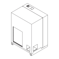
Provides an exploded view of the DRD265-500 (Ac) model assembly.
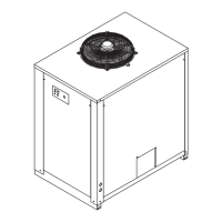
Provides an exploded view of the DRD700-1000 (Ac) model assembly.
Provides an exploded view of the DRD700-1000 (Wc) model assembly.
Shows external dimensions and mounting points for the DRD265-500 (Ac).
Shows external dimensions and mounting points for the DRD700-1000 (Ac).
Shows external dimensions and mounting points for the DRD700-1000 (Wc).
Illustrates the refrigerant circuit for the DRD265-500 (Ac) model.
Illustrates the refrigerant circuit for DRD700-1000 (Ac/Wc) models.
Illustrates the refrigerant circuit for DRD250-340 (Ac/Wc) models.
Layout of the electrical panel for DRD265-500 (230V/3/60Hz Ac).
Main wiring diagram for DRD265-500, including power, motors, and controls.
Wiring for controls, sensors, and serial communication on DRD265-500.
Arrangement of electronic cards and terminal blocks for DRD265-500.
Layout of the electrical panel for DRD265-500 (460V/3/60Hz Ac).
Main wiring diagram for DRD265-500, covering power and motor connections.
Wiring for controls, sensors, and serial communication on DRD265-500.
Arrangement of electronic cards and terminal blocks for DRD265-500.
Layout of the electrical panel for DRD700-800 (230V/3/60Hz Ac/Wc).
Main wiring diagram for DRD700-800, covering power and motor connections.
Wiring for controls, sensors, and serial communication on DRD700-800.
Arrangement of electronic cards and terminal blocks for DRD700-800.
Layout of the electrical panel for DRD700-1000 (460V/3/60Hz Ac/Wc).
Main wiring diagram for DRD700-1000, covering power and motor connections.
Wiring for controls, sensors, and serial communication on DRD700-1000.
Arrangement of electronic cards and terminal blocks for DRD700-1000.
