English
2/6
DRD 265-1000
2 Introduction
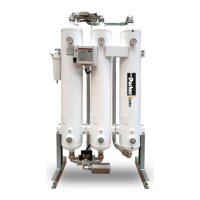
This manual refers to refrigeration dryers designed to guarantee high
quality in the treatment of compressed air.
2.1 Transport
The packed unit must:
• remain upright;
• be protected against atmospheric agents;
• be protected against impacts.
2.2 Handling
Use a fork-lift truck suitable for the weight to be lifted, avoiding any type
of impact.
2.3 Inspection
a) All the units are assembled, wired, charged with refrigerant and oil
and tested under standard operating conditions in the factory;
b) on receiving the machine check its condition: immediately notify the
transport company in case of any damage;
c) unpack the unit as close as possible to the place of installation.
2.4 Storage
If several units have to stacked, follow the notes given on the packing.
Keep the unit packed in a clean place protected from damp and bad
weather.
3 Installation
Y For the correct application of the warranty terms, follow the instruc-
tions given in the start-up report, ll it in and send it back to Seller.
In places with re hazard, provide for a suitable re-extinguishing sys-
tem.
3.1 Procedures
Install the dryer inside, in a clean area protected from direct atmospheric
agents (including sunlight).
Y Comply with the instructions given in par. 8.2 and 8.3.
All dryers must be tted with adequate pre- ltration near the dryer air
inlet. Seller is excluded any obligation of compensation or refund for any
direct or indirect damage caused by its absence
Y Pre- lter element (for 3 micron ltration or better) must be replaced
at least once a year, or sooner as per manufacturer recommendations.
Y Correctly connect the dryer to the compressed air inlet/outlet con-
nections.
3.2 Operating space
Leave a space of 1 m (60 inches) around the unit.
Leave a space of 2 m (80 inches) above dryer models with vertical con-
densation air expulsion.
3.3 Versions
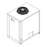
Air-cooled version (Ac)
Do not create cooling air recirculation situations. Do not obstruct the
ventilation grilles.
Water-cooled version (Wc)
If not provided in the supply, t a mesh lter on the condensation water
inlet.
Y, Inlet condensation water characteristics:
Temperature ≥50°F (10°C) CL
-
<50 ppm
ΔT IN/OUT 5-15°C CaCO
3
70-150 ppm
Max % glycol 50 O
2
<0.1 ppm
Pressure
43.5-145 PSIg
(3-10 barg)
Fe <0.2 ppm
PH 7.5-9 NO
3
<2 ppm
Electrical
conductivity
10-500 μS/cm HCO
3
- 70-300 ppm
Langelier
saturation
index
0-1 H
2
S <0.05 ppm
SO
4
2-
<50 ppm CO
2
<5 ppm
NH
3
<1 ppm Al <0.2 ppm
Please note that for special cooling water types such as demineralized,
deionized or distilled it is necessary to contact the manufacturer to verify
which kind of condenser should be used since the standard material may
not be suitable.
3.4 Tips
To prevent damage to the internal parts of the dryer and air compres-
sor, avoid installations where the surrounding air contains solid and/or
gaseous pollutants (e.g. sulphur, ammonia, chlorine and installations in
marine environments).
The ducting of extracted air is not recommended for versions with axial
fans.
3.5 Electrical connection
Use approved cable in conformity with the local laws and regulations (for
minimum cable section, see par. 8.3).
Install a differential thermal magnetic circuit breaker with contact open-
ing distance 3 mm ahead of the system (RCCB - IDn = 0.3A) (see the
relevant current local regulations).
The nominal current In of the magnetic circuit breaker must be equal to
the FLA with an intervention curve type D.
3.6 Condensate drain connection
Y Make the connection to the draining system, avoiding connection in
a closed circuit shared by other pressurized discharge lines. Check the
correct ow of condensate discharges. Dispose of all the condensate in
conformity with current local environmental regulations.
4 Commissioning
4.1 Preliminary checks
Before commissioning the dryer, make sure:
• installation was carried out according that given in the section 3;
• the air inlet valves are closed and that there is no air ow through the
dryer;
• the power supply is correct;
• with Wc version, open the cooling water circuit a few minutes before
starting the dryer.
4.2 Starting
a) Start the dryer before the air compressor;
b) switch the power on by turning the MAIN SWITCH “
&
” to
“I ON”: the POWER LED (2) lights up turning yellow; the crankcase
heater will now start heating .
! THE CRANKCASE HEATER MUST BE SWITCHED ON 12 HOURS
BEFORE STARTING THE DRYER.
Failure to comply with this rule may cause serious damage to the
compressor.
Once the crankcase is preheated, press the ON button on the control
panel.
c) press
x
: the POWER LED (2) turns green and the compressor
switches on; the dew point is displayed.
Y Fans (Ac version): if connected with the wrong phase sequence
they turn in the opposite direction, with the risk of being damaged (in this
case the air exits the dryer cabinet from the condenser grilles instead
from the fan grille - see par. 8.6 and 8.7 for correct air ow); immediately
invert two phases.
d) Wait 5 minutes, then slowly open the air inlet valve;
e) slowly open the air outlet valve: the dryer is now drying.
Phases Monitor
If appears to display the alarm “CP “, during the start up of the dryer, the
user must verify the wiring of the input terminals of the disconnecting
switch of the dryer.
4.3 Operation
• Leave the dryer on during the entire period the air compressor is work-
ing;
• The dryer operates in automatic mode, therefore eld settings are not
required;
• In the event of unforeseen excess air ows, by-pass to avoid over-
loading the dryer.
• Avoid air inlet temperature uctuations.
4.4 Stop
a) Stop the dryer 2 minutes after the air compressor stops or in any
case after interruption of the air ow;
b) make sure compressed air does not enter the dryer when the dryer is
disconnected or if an alarm occurs.
 Loading...