Do you have a question about the Parker PSE and is the answer not in the manual?
Explains the necessity of keeping and reading the manual for safe operation.
Describes symbols for danger, equipment damage, and required technician presence.
Provides essential safety instructions for machine operation and risk avoidance.
Lists residual risks, exposure methods, and necessary precautions for safe operation.
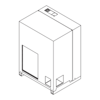
Guidelines for safely transporting the packed unit, emphasizing upright position and protection.
Instructions for safe handling using a forklift, avoiding impacts.
Steps for inspecting the unit upon receiving it, checking for damage.
Recommendations for storing the unit, keeping it packed, clean, and protected from weather.
Follow start-up report instructions, fill it in, and send it back. Consider fire risk.
Specifies required clearance around the unit and above for vertical air expulsion.
Details for air-cooled (Ac) and water-cooled (Wc) versions regarding ventilation and water inlet.
Advice to prevent damage, avoid pollutants, and handle air ducting.
Use approved cables, install circuit breakers, and adhere to nominal current requirements.
Connect to draining system, avoid closed circuits, check flow, and dispose of condensate responsibly.
Ensures installation completion, correct power supply, and cooling water readiness.
Sequence for starting the dryer before the compressor, crankcase heater, and operational steps.
Keep dryer on during compressor operation, use bypass for excess flow, avoid temperature fluctuations.
Procedure for stopping the dryer after the compressor, ensuring no air entry, and powering off.
Explains the main power switch (QS) and control buttons for incrementing/decrementing values.
Describes symbols for compressor/dryer status, alarms, and warnings on the control panel.
Instructions for setting the temperature measurement unit and accessing general menus.
Details three modes for condensate drain: capacitive, timed, and external.
Procedure to enter menus for setting remote ON/OFF functionality.
Steps to access and set the continuous or cycling function mode for the dryer.
How to view current and previous alarms and warnings that have occurred.
Step-by-step guide to set the clock and date, noting memory limitations.
Overview of the touch control panel layout and basic navigation.
Explains symbols and their meanings on the touch control panel for status and functions.
Accessing menus for probes, input, output, and serial number for detailed information.
Setting measurement unit, local/remote start, alarm signaling, and restoring default parameters.
How to select and set the continuous or cycling operating mode.
Accessing and viewing alarm and warning pages, and performing resets.
Explains the status of various digital inputs like Local ON/OFF and Compressor Protection.
Describes the status of digital outputs such as General Alarm, Compressor, and Plant Status.
Quick access to change measurement units, drain settings, local/remote, and view probes.
Crucial safety steps before maintenance: ensure no pressure and disconnect from power.
Information about R513A refrigerant, its properties, and safety precautions for handling.
Details scheduled maintenance activities and intervals for optimal performance and reliability.
Procedures for recovering refrigerant and oil, and guidelines for recycling components.
Flowchart to diagnose faults, identify causes, and find appropriate remedies for common issues.
Explains various symbols used in the manual, their multilingual translations, and meanings.
Defines symbols for analog inputs, their reference codes, and descriptions.
Defines symbols for digital inputs, their reference codes, and descriptions.
Details components specific to models with timed drains and external drain purgers.
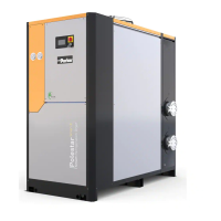
Identifies key components like air compressor, dryer, bypass unit, and filters with multilingual labels.
Shows required piping materials and important safety valve information for pressure.
Labels system components, safety, and vibration notes.
Details technical specifications like weight, refrigerant, temperatures, electrical data, and connections.
Provides calibration values for hot gas valve, pressure, fan speed, and pressure switches.
Lists preventive maintenance kits, electrical kits, compressor kits, and fan kits with part numbers.
Details spare parts for refrigerant condenser, sweep exchanger, filter, and solenoid valves.
Lists spare parts for various sensors (dew point, evaporator, discharge) and switches.
Illustrates the assembly of PSE120/180 Ac model, with numbered components for identification.
Shows the exploded view of the PSE220/350 Ac model, detailing parts and their locations.
Provides an exploded view of the PSE220/350 Wc model, identifying all major components.
Displays overall dimensions, connection points, and airflow for the PST120-180 Ac unit.
Shows the physical dimensions and the location of various connections for the PSE 220-350 Ac.
Provides dimensional data and connection port details for the PSE 220-350 Wc model.
Illustrates the refrigerant circuit for the PSE120-180 Ac, linking symbols to component descriptions.
Displays the refrigerant circuit for PSE220-350 Ac with a detailed list of components.
Shows the refrigerant circuit for the PSE220-350 Wc model, detailing component connections.
Illustrates the physical layout of components within the electrical panel for PSE120-180.
Details main power connections and wiring for compressor and fan motors.
Shows wiring for analog inputs (sensors) and outputs (transmitters) to the control system.
Illustrates wiring connections for digital outputs, controlling relays and solenoids.
Details wiring for digital inputs, including pressure switches and remote control signals.
Covers wiring for remote ON/OFF, general alarm, and communication interfaces (RS-485, LAN).
Table detailing nominal voltage, current, power, and frequency for compressor and fan motors.
Visual representation of the electrical panel layout for touch-screen models.
Wiring diagram for main power, general switch, fuses, and auxiliary transformer.
Shows wiring for analog outputs and communication interfaces like RS-485.
Details wiring for various analog inputs, including temperature and pressure sensors.
Illustrates wiring for digital inputs and outputs, such as pressure switches and solenoid valves.
Wiring connections for expansion modules, including analog inputs and communication.
Wiring for digital inputs and outputs on expansion modules, such as automatic switches.
Wiring for terminal blocks, digital outputs, and communication interfaces (RS-485).
| Category | Dryer |
|---|---|
| Power Source | Electric |
| Voltage | 220-240V |
| Overheat Protection | Yes |
| Frequency | 50Hz |
| Color | White |
| Material | Plastic |
| Model | Parker PSE |