iii
Table of Illustrations
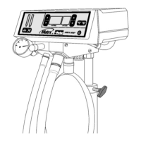
Figure 1. Outside View of a Typical Digital MDM® Cabinet Mount with Flush
Mounted Bag Tee/Scavenging Valve ....................................................................... 3
Figure 2. Installation of Demand Valves ................................................................................... 4
Figure 3. Digital MDM® Mixer Head Configurations ................................................................. 5
Figure 4. Screw and Tee Nut Adjustment ................................................................................. 5
Figure 5. Digital MDM® Mixer Head Installation ....................................................................... 6
Figure 6. Flush Mounting the Bag Tee and Scavenging Control Valve .................................... 6
Figure 7. Surface Mounting the Bag Tee and Scavenging Control Valve ................................ 7
Figure 8. Mounting the Bag Tee and Scavenging Control Valve Inside the Cabinet................ 8
Figure 9. Connection Schematic ............................................................................................... 9
Figure 10. Installation of Rubber Goods ..................................................................................... 9
Figure 11. Installation of Power Cord .......................................................................................... 9
 Loading...