Bulletin MSG30-3245-INST/UK
Installation Manual
11
Parker Hannifin
Pump & Motor Division Europe
Chemnitz, Germany
Axial Piston Pump
Series PV, series 44 and higher
10. Compensator accessories
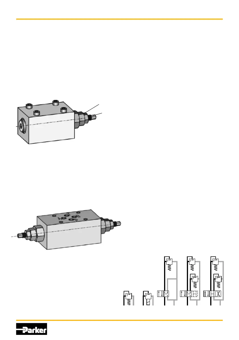
10.1 Pressure relief pilot valve, code
PVAC1P...
The pressure relief pilot valve code PVAC1P... is opti-
mally tuned for the requirements of the compensator
valves of the series PV. It has a mounting interface
NG6 according to DIN 24340 and can be mounted
directly on top of all compensator valves with the
topside mounting interface.
Such a valve is only necessary for the compensators
with elbow manifold (...MT1 and ...UPR) and for the
versions without integrated pressure pilot cartridge
(compensator code ends with..Z). Al other versions
include an integrated pilot valve.
lock nut
set screw
After loosening the lock nut SW13 an adjustment of
the compensating pressure for the pump is possible
in a range of approx. 20 bar up to 350 bar.
The pressure pilot valve is also available with a DIN
lock.
10.2 Multiple pressure pilots PVA-
C1E..., PVAC2P..., PVAC2E... und
PVAC2M...
For multiple pressure pilots, codes PVAC2P...,
PVAC2E... and PVAC2M... a sandwich valve with
two direct-action pressure cartridge valves is used
to pilot the pump.
For code PVAC2P... a single solenoid directional
control valve is included for pressure selection. The
valve switches between low pressure setting and
high pressure setting. During low pressure both pilot
cartridges are connected to the compensator, in the
high pressure setting (solenoid energized) only the
A-side cartridge is connected. Therefore the B-side
pilot needs to be set for lower pressure. The direc-
tional control valve series D1VW has spool code 6.
For code PVAC2E... for pressure selection a two-
solenoid DCV is included, which selects between low
pressure setting, high pressure setting and stand-by
pressure. In neutral position both cartridges are con
nected to the compensator valve. The lower pressure
defines the compensating pressure of the pump.
When the A solenoid (B-side) of the DCV is energized
only the A-side cartridge is connected; the (higher)
pressure adjusted there defines the compensating
pressure.
When solenoid B is energized the valve spool con-
nects all four ports. Then the spring chamber of the
compensator valve is directly relieved to the case
drain of the pump, the pump compensates at mini-
mum compensating pressure (stand-by).
The directional control valve series D1VW has spool
code 55. This spool code is used to avoid a blocked
spool position during transient.
This version is recommended, when during a ma-
chine cycle the pressure is to be switched between
high and low.
For code PVAC2M... also a dual solenoid valve is
used. In neutral position all four ports are connected.
The compensator spring chamber is releived to case
drain, the pump is compensating at min. compensat-
ing pressure (stand-by).
When energizing solenoid A (B-side) the spring
chamber is connected to the A-side pilot cartridge;
the pressure adjusted here controls the pump.
When solenoid B is energized the spring chamber
of the compensator is connected to pilot cartridge B;
then the pressure adjusted on this cartridge defines
the pump compensating pressure. The DCV of series
D1VW has spool code 2.
This version should be used, when stand-by operation
should be the default situation.
Code PVAC1E... is similar to code PVAC2P..., with the
exception, that only one pilot cartridge is installed. In
neutral position of the D1VW the stand-by pressure
is selected.
Additional information can be found in:
compensator spare parts manual PVI-PVC-UK-45
compensator accessories spare parts manual
PVI-PVAC-UK
pumps spare parts manuals PVI-***-UK-45 with *** =
BG1 to BG5 according to pump frame size.
P
T
P
T
P
T
P
T
P
T
p1
p1
p1
p2 p2
(>p2)
A
B
P T
A
B
P T
A
B
P T
PVACPPPVAC1P... PVAC2P...
(PVAC2E...)
PVAC1E...
PVAC2M...
 Loading...


