MI-104
Parker Hannifin Corporation
Instrumentation Valve Division
Jacksonville, Alabama
6
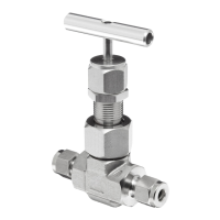
VALVE CONNECTOR MAKE-UP INSTRUCTIONS
MALE AND FEMALE PIPE PORTS
Wrench flats are provided on the Valve Body. It is recommended a smooth- jawed wrench or vise be used to grip the Valve Body.
1. On the male threaded part of the connection, apply a high quality pipe joint compound or PTFE tape made for this purpose. When PTFE tape is
used, it is recommended two full turns of tape be applied. PTFE tape should not be overhanging or covering the first thread
2. Engage the Valve and the other component part together, until hand-tight.
3. With a proper wrench, holding both the Valve and the component part, continue to tighten to achieve a leak-tight joint.
ULTRASEAL CONNECTIONS
1. Insert the proper O-Ring into the UltraSeal fittings O-Ring groove. Position the UltraSeal gland sealing face against the O-Ring, and then advance
the Nut to a finger-tight position.
2. A positive seal is obtained by advancing the Nut no less than 1/4 turn from the finger-tight position. Proper UltraSeal make-up is achieved when
a sharp rise in required application torque occurs, which indicates proper seal face contact and O-Ring seal compression into the UltraSeal
groove.
VACUSEAL CONNECTIONS
1. A positive seal is obtained by advancing the Nut 1/8 turn from the finger-tight position.
2. A new gasket should be installed upon each fitting re-make to insure system pressure integrity.
TUBE FITTING CONNECTIONS
1. Insert the tube into the Valve port until the tube bottoms out in the Valve Body. Care should be exercised to insure the tube is properly aligned with
the Valve Body and port.
2. Normal make-up for US Customary port sizes 1 thru 3 (1/16 thru 3/16 inch) and SI port sizes 2 thru 4 (2 thru 4 mm) is 3/4 turn from finger tight.
Normal make-up for US Customary port sizes 4 thru 16 (1/4 thru 1 inch) and SI port sizes 5 thru 25 (5 thru 25 mm) is 1 1/4 turn from finger tight.
For larger port sizes consult Parker Ferrule Presetting Tool Instructions.
PLEASE FOLLOW THE ABOVE DIRECTIONS FOR COUNTING THE NUMBER OF TURNS FOR PROPER FITTING MAKE-UP. DO
NOT MAKE-UP TUBE FITTINGS BY TORQUE OR FEEL. VARIABLES SUCH AS TUBING AND FITTING TOLERANCES, TUBE
WALL THICKNESS, AND THE LUBRICITY OF NUT LUBRICANTS CAN RESULT IN AN IMPROPERLY ASSEMBLED TUBE FITTING
CONNECTION.
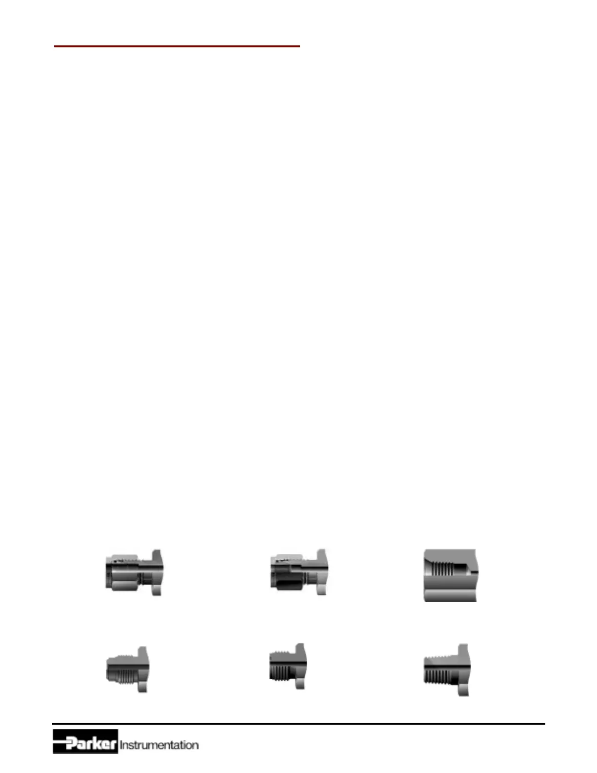
A -Two ferrule A-LOK
®
compression port
M -ANSI/ASME B1.20.1
External pipe threads
Z -Single ferrule CPI
TM
compression port
Q -UltraSeal face
seal port
F -ANSI/ASME B1.20.1
Internal pipe threads
V -VacuSeal face
seal port
 Loading...


