7
Downtime Cleaning Operation
1. Turn the CLEAN switch to the ON position. The PWR light will be
ON.
2. When the CLEAN CONTROL contacts (#13 and 14) are shorted,
the CLEAN light will be ON.
3. When the CLEAN CONTROL contacts open, the CLEAN light will
flash for the duration of the cleaning cycle.
4. After the 60-second blower coast down delay, the valve output
(V and N) will turn on for the selected length of time (100 or 150mS).
5. If more than one pulse is selected (2, 4 or 6), there will be a 10 or
30 second delay as selected between the pulses.
6. When the cleaning cycle is complete, the CLEAN light will turn OFF
and the control board will wait for the CLEAN CONTROL contacts to
close again.
If at any time during the cleaning cycle the CLEAN CONTROL con-
tacts close, the cleaning cycle will be aborted, the CLEAN light will
stop flashing, and the unit will wait for the CLEAN CONTROL con-
tacts to open. The unit will NOT remember how many pulses were
previously performed; and the cleaning cycle will start again from the
beginning. The position of the four "white" switches on S1 determine
the number of pulses, the length of the pulse and the delay between
pulses. The position of the switches are read when the CLEAN CON-
TROL contacts open, and will not affect the cleaning cycle if changed
during a cleaning cycle. (See Figure 5 for Cleaning Control Switch
Settings)
Upon motor/blower shutdown, downtime cleaning will only be per-
formed if the CLEAN SWITCH is in the ON position before the motor/
blower is turned OFF. During downtime cleaning, the CLEAN light will
flash for the duration of the cycles selected.
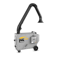
5. Operation
5.1 Start-Up
1. Position unit in desired location.
NOTE: Do not attempt to move the portable unit by pulling on the
swing arm or hood. Use the fullwidth, bar-type handle on the back of
the unit to push the V Series into the desired location. After the unit is
situated, use the locks on the rear wheel casters to secure the unit.
2. Plug the unit into a properly grounded electrical receptacle.
6
Revised 08/09
V SERIES
Cartridge Dust Collector
6. SERVICE
Figure 7. Rear Access
61-10039-0001
Collected dust may be hazardous. Consult proper
authorities for handling and disposal.
4. The filter monitor gauge should read between
0.1" and 0.5" w.g. while unit is operating with
clean filters.
5. The discharge plenum on the V Series collector
can be rotated in 90
increments to direct the
discharge air in multiple directions. The discharge
housing will be factory installed with the discharge
pointing towards the floor as shown in Figure 7.
Collecting Particles
1. Locate the unit, arm and hood in the best position
to collect contaminants as generated by the
process or operation, and where operator
interference is minimal.
2. Position the hood to minimize the influence of
cross drafts from outside air sources or other
operations.
3. Position the hood slightly higher than the source,
with the face of the hood approximately 45° from
horizontal. The hood shape is designed for high-
velocity pick up. It should be located as close to
the source as practical and no further than 14-16"
from the contaminant source.
3. Check diaphragm valves to ensure
proper pulse
cleaning. With the cleaning cycle activated, the valve
should pulse at approximately 10-second intervals.
Remove lid of control panel enclosure to view the
timer.
4. Check the filter monitor gauge at start-up. The
cleaning system should be activated when the gauge
has increased 0.5" w.g. above the start-up pressure
drop. Allow unit to pulse clean until the original
reading is achieved or until the gauge reading will
not decrease after six consecutive pulses.
5.2 CHECKLIST
1. Check the clean air outlet. Discharge air should
remain visibly clean. If a leak should develop, it will
be first noticed after a cleaning pulse as a puff of
dust.
2. Check pressure drop on the pressure gauge
(see Figure 6). Pressure drop across elements is
considered normal between 0.5-5.0" w.g. Pressure
drop will generally read between 1-2" for “seasoned”
filters.
The following procedure requires access to an area of
the unit where high voltage is present. Access should
be restricted to qualified personnel.
Figure 6. Control Panel Layout Detail
61-10039-0002
3. Turn the unit on by pushing the "Power" rocker
switch to the ON position (refer to Figure 6). On
3-phase units, fan rotation will need to be verified
by matching fan rotation with the rotation decal on
the blower housing. Rotation should be clockwise
as viewed from the motor or drive side. Any two
motor starter leads should be reversed if the
rotation is not correct.
4. The filter monitor gauge should read between 0.1” and 0.5”
w.g. while unit is operating with clean filters.
5. The discharge plenum on the V Series collector can be rotated
in 90 increments to direct the discharge air in multiple directions.
The discharge housing will be factory installed with the discharge
pointing towards the floor as shown in Figure 7.
Collecting Particles
1. Locate the unit, arm and hood in the best position to collect
contaminants as generated by the process or operation, and
where operator interference is minimal.
2. Position the hood to minimize the influence of cross drafts from
outside air sources or other operations.
3. Position the hood slightly higher than the source, with the face
of the hood approximately 45° from horizontal. The hood shape
is designed for high velocity pick up. It should be located as close
to the source as practical and no further than 14-16” from the
contaminant source.
4. Check the filter monitor gauge at start-up. The cleaning sys-
tem should be activated when the gauge has increased 0.5” w.g.
above the start-up pressure drop. Allow unit to pulse clean until
the original reading is achieved or until the gauge reading will not
decrease after six consecutive pulses.
5.2 Checklist
1. Check the clean air outlet. Discharge air should remain visibly
clean. If a leak should develop, it will be first noticed after a clean-
ing pulse as a puff of dust.
2. Check pressure drop on the pressure gauge (see Figure 6).
Pressure drop across elements is considered normal between
0.5-5.0” w.g. Pressure drop will generally read between 1-2” for
“seasoned” filters.
The following procedure requires access to an area
of the unit where high voltage is present. Access
should be restricted to qualied personnel.
3. Check diaphragm valves to ensure proper pulse cleaning. With
the cleaning cycle activated, the valve should pulse at approximate-
ly 10-second intervals. Remove lid of control panel enclosure to
view the timer.
6
Revised 08/09
V SERIES
Cartridge Dust Collector
6. SERVICE
Figure 7. Rear Access
61-10039-0001
Collected dust may be hazardous. Consult proper
authorities for handling and disposal.
4. The filter monitor gauge should read between
0.1" and 0.5" w.g. while unit is operating with
clean filters.
5. The discharge plenum on the V Series collector
can be rotated in 90
increments to direct the
discharge air in multiple directions. The discharge
housing will be factory installed with the discharge
pointing towards the floor as shown in Figure 7.
Collecting Particles
1. Locate the unit, arm and hood in the best position
to collect contaminants as generated by the
process or operation, and where operator
interference is minimal.
2. Position the hood to minimize the influence of
cross drafts from outside air sources or other
operations.
3. Position the hood slightly higher than the source,
with the face of the hood approximately 45° from
horizontal. The hood shape is designed for high-
velocity pick up. It should be located as close to
the source as practical and no further than 14-16"
from the contaminant source.
3. Check diaphragm valves to ensure
proper pulse
cleaning. With the cleaning cycle activated, the valve
should pulse at approximately 10-second intervals.
Remove lid of control panel enclosure to view the
timer.
4. Check the filter monitor gauge at start-up. The
cleaning system should be activated when the gauge
has increased 0.5" w.g. above the start-up pressure
drop. Allow unit to pulse clean until the original
reading is achieved or until the gauge reading will
not decrease after six consecutive pulses.
5.2 CHECKLIST
1. Check the clean air outlet. Discharge air should
remain visibly clean. If a leak should develop, it will
be first noticed after a cleaning pulse as a puff of
dust.
2. Check pressure drop on the pressure gauge
(see Figure 6). Pressure drop across elements is
considered normal between 0.5-5.0" w.g. Pressure
drop will generally read between 1-2" for “seasoned”
filters.
The following procedure requires access to an area of
the unit where high voltage is present. Access should
be restricted to qualified personnel.
Figure 6. Control Panel Layout Detail
61-10039-0002
3. Turn the unit on by pushing the "Power" rocker
switch to the ON position (refer to Figure 6). On
3-phase units, fan rotation will need to be verified
by matching fan rotation with the rotation decal on
the blower housing. Rotation should be clockwise
as viewed from the motor or drive side. Any two
motor starter leads should be reversed if the
rotation is not correct.
3. Turn the unit on by pushing the "Power" rocker switch to the
ON position (refer to Figure 6). On 3-phase units, fan rotation will
need to be verified by matching fan rotation with the rotation decal
on the blower housing. Rotation should be clockwise as viewed
from the motor or drive side. Any two motor starter leads should
be reversed if the rotation is not correct.
!
WARNING
 Loading...