5
3
Revised 08/09
V SERIES
Cartridge Dust Collector
See below for the amperage requirements of your unit,
given the horsepower and power supply. The unit
nameplate will provide the electrical specifications of
your V Series system.
Motor HP
1.5
1.5
1.5
1.5
1.5
1.5
3
3
3
3
Power Supply
115/1/60
230/1/60
200/3/60
230/3/60
460/3/60
575/3/60
200/3/60
230/3/60
460/3/60
575/3/60
Amp Draw
16.4
8.4
5.2
4.8
2.4
1.9
8.4
7.8
3.9
3.1
Standard Unit Options:
HEPA After Filter, Carbon Odor After Filter, Pre-Wired
Motor Starter Panels
Filter Media Options:
Protura
®
Nanofiber, Protura
®
Nanofiber Fire Retardant,
Poly-Fiberglass, Spun-Bond Polyester
See Table 1 on page 2 to see the operating
specifications on your V Series system.
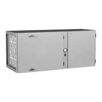
4. INSTALLATION
4.1 OFF LOADING AND INSPECTION
The V Series dust collector is shipped in two or three
containers depending on the configuration and options
selected. The first consists of the unit cabinet and
filtration components. Other container(s) may contain
the extraction arm, downdraft bench, etc.
Upon receipt of your unit, check for any shipping
damage. A damaged carton indicates that the
equipment may have received rough handling during
shipping that may have caused internal damage. Notify
your delivery carrier and enter a claim if any damage is
found.
Remove the filter access cover (located on the front of
the unit) by turning the black knob counterclockwise to
release the cover. Examine the seal between the
tubesheet (the vertical panel between the blower
section and the filter section) and filter. Make sure filter
or gasket has not become displaced during shipment
(refer to Section 6.1, Cartridge Filter Removal and
Replacement). Replace covers once inspection is
complete.
4.2 INSTALLATION
Different models of the V Series collector require
different assembly techniques. Please see the
techniques in the subsequent sections for
your V Series dust collector.
All models of the V Series will require minimum
clearances and access in order to perform routine
maintenance and service. Be sure to leave access for
filter removal, the dust drawer release lever and
blower/pulse valve access through the discharge
panel as shown in Figure 1.
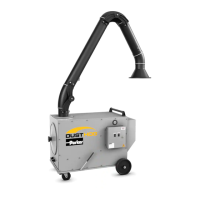
4.2.1 PORTABLE INSTALLATION (VP MODEL)
The top of the V Series cabinet has either one set
of six (VP-750) or eight (VP-1500) threaded studs to
mount the swing arm. The necessary hardware is
pre-assembled the studs. When mounting the arms
on the unit, a ceiling height of about 10’ is required for
adequate clearance. Two people are suggested for
positioning the swing arm and securing into place.
1. Remove the swing arm from its shipping
containers and assemble per the swing arm
manual provided.
2. Remove nuts, lock washer and flat washer from
the studs on the cabinet (refer to Figure 2).
3. Position flange gasket(s) inside the protruding
studs on top of the unit (refer to Figure 2).
4. Position the swing arm mounting base into place
over the mounting studs. Ensure gasket is
positioned properly between unit and base
flange. Secure swing arm to cabinet top with the
recently removed hardware (refer to Figure 2).
Avoid sharp pulls on the arm or hood as well as
over-tightening the pivot section since damage to
the arm components could result.
Figure 2. Swing Arm Installation Detail
Table 2 - Unit Amperage Requirements
61-10036-0002
See below for the amperage requirements of your unit, given the
horsepower and power supply. The unit nameplate will provide the
electrical specifications of your V Series system.
Standard Unit Options:
HEPA After Filter, Carbon Odor After Filter, Pre-Wired Motor Starter
Panels
Filter Media Options:
Protura® Nanofiber, Protura® Nanofiber Fire Retardant, Poly-Fiber-
glass, Spun-Bond Polyester
See Table 1 on page 2 to see the operating specifications on your V
Series system.
4. Installation
4.1 Off Loading and Inspection
The V Series dust collector is shipped in two or three containers
depending on the configuration and options selected. The first consists
of the unit cabinet and filtration components. Other container(s) may
contain the extraction arm, downdraft bench, etc.
Upon receipt of your unit, check for any shipping damage. A damaged
carton indicates that the equipment may have received rough handling
duringshipping that may have caused internal damage. Notify your de-
livery carrier and enter a claim if any damage is found.
Remove the filter access cover (located on the front of the unit) by
turning the black knob counterclockwise to release the cover. Examine
the seal between the tubesheet (the vertical panel between the blower
section and the filter section) and filter. Make sure filter or gasket has
not become displaced during shipment (refer to Section 6.1, Cartridge
Filter Removal and Replacement). Replace covers once inspection is
complete.
4.2 Installation
Different models of the V Series collector require different assembly
techniques. Please see the techniques in the subsequent sections for
your V Series dust collector.
All models of the V Series will require minimum clearances and access
in order to perform routine maintenance and service. Be sure to leave
access for filter removal, the dust drawer release lever and blower/
pulse valve access through the discharge panel as shown in Figure 1.
4.2.1 Portable Installation (VP Model)
The top of the V Series cabinet has either one set of six (VP-750) or
eight (VP-1500) threaded studs to mount the swing arm. The neces-
sary hardware is pre-assembled the studs. When mounting the arms
on the unit, a ceiling height of about 10’ is required for adequate clear-
ance. Two people are suggested for positioning the swing arm and
securing into place.
1. Remove the swing arm from its shipping containers and assem-
ble per the swing arm manual provided.
2. Remove nuts, lock washer and flat washer from the studs on the
cabinet (refer to Figure 2).
3. Position flange gasket(s) inside the protruding studs on top of the
unit (refer to Figure 2).
4. Position the swing arm mounting base into place over the mount-
ing studs. Ensure gasket is positioned properly between unit and
base flange. Secure swing arm to cabinet top with the recently re-
moved hardware (refer to Figure 2). Avoid sharp pulls on the arm or
hood as well as over-tightening the pivot section since damage to
the arm components could result.
4.2.2 Downdraft Table Assembly (VB Model)
The V Series downdraft table (VB) comes packaged, requiring some as-
sembly before using. Follow the steps below to complete the assembly.
1. Begin by securing the two side panels as shown in Figure 3.
Thread all four fastening knobs into the cabinet leaving enough
space for the side panel to fit over top of threaded knob stud.
2. Lower each panel as shown onto the knob studs and then
tighten knobs until panel is secure.
3. Lower the back panel into rear aligning tray and side panel guide
slots.
3
Revised 08/09
V SERIES
Cartridge Dust Collector
See below for the amperage requirements of your unit,
given the horsepower and power supply. The unit
nameplate will provide the electrical specifications of
your V Series system.
Motor HP
1.5
1.5
1.5
1.5
1.5
1.5
3
3
3
3
Power Supply
115/1/60
230/1/60
200/3/60
230/3/60
460/3/60
575/3/60
200/3/60
230/3/60
460/3/60
575/3/60
Amp Draw
16.4
8.4
5.2
4.8
2.4
1.9
8.4
7.8
3.9
3.1
Standard Unit Options:
HEPA After Filter, Carbon Odor After Filter, Pre-Wired
Motor Starter Panels
Filter Media Options:
Protura
®
Nanofiber, Protura
®
Nanofiber Fire Retardant,
Poly-Fiberglass, Spun-Bond Polyester
See Table 1 on page 2 to see the operating
specifications on your V Series system.
4. INSTALLATION
4.1 OFF LOADING AND INSPECTION
The V Series dust collector is shipped in two or three
containers depending on the configuration and options
selected. The first consists of the unit cabinet and
filtration components. Other container(s) may contain
the extraction arm, downdraft bench, etc.
Upon receipt of your unit, check for any shipping
damage. A damaged carton indicates that the
equipment may have received rough handling during
shipping that may have caused internal damage. Notify
your delivery carrier and enter a claim if any damage is
found.
Remove the filter access cover (located on the front of
the unit) by turning the black knob counterclockwise to
release the cover. Examine the seal between the
tubesheet (the vertical panel between the blower
section and the filter section) and filter. Make sure filter
or gasket has not become displaced during shipment
(refer to Section 6.1, Cartridge Filter Removal and
Replacement). Replace covers once inspection is
complete.
4.2 INSTALLATION
Different models of the V Series collector require
different assembly techniques. Please see the
techniques in the subsequent sections for
your V Series dust collector.
All models of the V Series will require minimum
clearances and access in order to perform routine
maintenance and service. Be sure to leave access for
filter removal, the dust drawer release lever and
blower/pulse valve access through the discharge
panel as shown in Figure 1.
4.2.1 PORTABLE INSTALLATION (VP MODEL)
The top of the V Series cabinet has either one set
of six (VP-750) or eight (VP-1500) threaded studs to
mount the swing arm. The necessary hardware is
pre-assembled the studs. When mounting the arms
on the unit, a ceiling height of about 10’ is required for
adequate clearance. Two people are suggested for
positioning the swing arm and securing into place.
1. Remove the swing arm from its shipping
containers and assemble per the swing arm
manual provided.
2. Remove nuts, lock washer and flat washer from
the studs on the cabinet (refer to Figure 2).
3. Position flange gasket(s) inside the protruding
studs on top of the unit (refer to Figure 2).
4. Position the swing arm mounting base into place
over the mounting studs. Ensure gasket is
positioned properly between unit and base
flange. Secure swing arm to cabinet top with the
recently removed hardware (refer to Figure 2).
Avoid sharp pulls on the arm or hood as well as
over-tightening the pivot section since damage to
the arm components could result.
Figure 2. Swing Arm Installation Detail
Table 2 - Unit Amperage Requirements
61-10036-0002
 Loading...