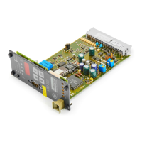
Digital Power Amplifier
Series VRD350 and VRD355Installation Manual
11
IA VRD UK.INDD RH 02.06
Parker Hannifin GmbH & Co. KG
Hydraulic Controls Division
Jumper Field for Actual Value Input
Classification of Application Cases
• Voltage input with terminating resistance R =
600kOhm:
Used for all proportional valves with displacement
transducers with mean voltages 6V and 7,5V.
• Voltage input without terminating resistance:
Used for potentiometric transmitter systems in
which the loop current is limited to smal values.
Linearity of the transmitter signal is maintained.
• Current input with load R = 100Ohm:
Used for all sensors with current output 0...20mA
or 4...20mA.
Terminal Connection Diagrams for the Standard
Feedback Transducers for Position-Controlled
Valves
Line socket Connector assignment
WLL NG10
1 - Output
2 - Supply (+24V)
3 - 0V
4 - not used
D*FS, RLL, WLL NG06
1 - Output
2 - Supply (+24V)
3 - 0V
4 - not used
5 - GND
DUR
1 - Output
2 - Supply (+24V)
3 - 0V

 Loading...