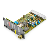
Digital Power Amplifier
Series VRD350 and VRD355Installation Manual
27
IA VRD UK.INDD RH 02.06
Parker Hannifin GmbH & Co. KG
Hydraulic Controls Division
3.12. Controller Parameters
When setting parameters P13 and P16,
the effect of parameter E2 and E14 must
be taken into account. E2 = 1 and E14
= 0 are used for position-controlled di-
rectional valves. E2 = 1 or 4 (with security function)
and E14 ≠ 0 is selected for external control circuits,
depending on the gain required. E14 specifies an
additional amplification.
E2 = 1, 2 and 4
P13 is the K
P,1
for smal deviations
P16 is the K
P,2
for large deviations
P15 is the switching threshold K
P,1
→ K
P,2
The division into two amplifications permits stable
controller settings, even with large deviations.
E2 = 3
Bypass control activated
P13 is the amplification K
PBp
of the bypass
branch
P16 is the amplification K
P
(P share) of the PID
controller
P15 has no function
E14 = 0 set.
• Parameter P14 can be used to program a
T-portion (delaying time function element). Effect
on P16.
• The integral portion is determined by P17 whilst
P18 is used to set a derivative element. The
integral function P17 is limited internally to the
maximum value. As soon as this is reached, the
LED “>>1OV“ on the display panel lights up.
• The time for a delayed action D-portion is set
with parameter P19.
• It is possible to fine tune the gain for the feed-
back signal by parameter P20 without changing
the hardware settings.
• With external controls, P17 = 0.00 in the basic
setting!
Sensor Type Zero point
Offset Adjustment Input
Signal → U11
Position
E11
Position
E12
Adjustment
Zero Point
Adjustment
Range Gain
7,5 ± 2V 7.5V 7.5V → 0V 1 1 3.9...9.9V 3.3...13
4...20mA 4mA 4mA → 0V 2 or 7 1 1.2...5.4mA 0.37...1.5
0...20mA 0mA not possible 3 or 8 0 - 0.37...1.5
0...10V 0V not possible 4 or 9 0 - 0.37...1.5
6 ± 2V 6V 6V → 0V 5 1 3.9...9.9V 3.3...13
0 ± 10V 0V not possible 6 0 - 0.37...1.5
7.5 ± 4.5V 7.5V 7.5 → 0V 10 1 3.9...9.9V 0.37...1.5

 Loading...