4
IA VRD UK.INDD RH 02.06
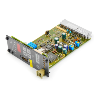
Digital Power Amplifier
Series VRD350 and VRD355Installation Manual
Parker Hannifin GmbH & Co. KG
Hydraulic Controls Division
1. Description and Design
Applications (general)
Amplifier card for driving proportional directional
valves, pressure and flow control valves. Suitable
for solenoid systems up to 3.5 A. Valves with spool
position feedback, and external closed loop control
circuits (e.g. pressure regulating circuits) can be
implemented with the closed loop control options.
Suitable for use on NC axes, especially where the
requirements for dynamic response and accuracy
are high.
Special Application of VRD355
Amplifier card without the front panel display and
operating elements for cost effective applications
where operation is via a serial interface or ABG35S
(must be ordered separately, No. 23.501 456).
The VRD350 / VRD355 Series is distinguished
by the following Features:
• PWM output stage with programmable current
controller.
• Adjustable parameters for all solenoid types up
to 3.5A.
• Digital setting and display of all parameters.
• High set value and feedback resolution
(<0.05%).
• No temperature or long-term drift.
• Precisely reproducible settings.
• Serial interface on the front panel for remote
parameter setting.
• Simple operation by 4 entry keys and 3-digit
LED display.
• Fault indication by numeric code.
• Variable dither amplitude and frequency.
• Gain for solenoids A and B can be set indepen-
dantly.
• Different valve characteristics are stored
on-board to enable linearisation.
• Set value simulation for simplified commission-
ing.
• Only a unipolar supply voltage is necessary
(24V).
• Internally adjustable time delay of output stages
after applying the enable signal.
• Integrated actual value recording.
• Robust, SMT technology.
Meaning of Symbols
Warning, danger for user.
Attention, possible damage to unit or
other capital assets.
Note, information, key function.
• Differential amplifier input for NC command
signal 0...±10V.
• Additional input for command signal specifica-
tion by 0...±10V.
• Integrated power supply for ±10V symmetrical
to 0V supply, each capable of carrying 10mA.
• 4 recallable command signals.
• “+” and “-”-direction externally set.
• Enable signal for output stages.
• Reset-Ramp for quick reset of ramp function.
• All external input signals for command signals,
direction, enable, reset ramp are electrically
isolated by opto-couplers.
• Status outputs “Error” and “Comparator” are
similarly electrically isolated by opto-couplers.
• Function indication by LEDs on front panel.
• In addition, for simpler commissioning and for
service purposes, test sockets are located on
the front panel for S6 (NC-command signal),
A (feedback value, where available), I
A
and I
B
(Measurement instruments R
i
>100kΩ).
 Loading...