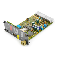
Digital Power Amplifier
Series VRD350 and VRD355Installation Manual
21
IA VRD UK.INDD RH 02.06
Parker Hannifin GmbH & Co. KG
Hydraulic Controls Division
On leaving the H mode, H parameter values are
no longer evaluated and thus are deactivated.
However, H parameter values are also internally
stored after leaving the H mode.
When H mode is selected again (always
H1 first), this is immediately effective,
with its corresponding value. It is rec-
ommended, therefore, that H1 and H2
parameters are set to 0.00 when commissioning
has been completed. The H-parameters are set =
0.00 when the supply voltage is switched off.
Display
H1...H2
Command signal simulation
Command signals as voltage 0...±9.99V
P-Parameters
Parameters can be set during operation. Any altera-
tion to P-Parameters with ⇑ and ⇓ keys is immedi-
ately effective. These parameters allow the amplifier
unit to be matched to the valve or the drive.
Display
P1 Offset (+30%... -30%) 0.00...+2.99
(See also page 25, section 3.3) 0.00...-2.99
Steps in 5 mV
Display in 10 mV steps
P2 Linearisation
Not active 0
Active 1...5
when using NC, select a linearisation!
(See also page 25, section 3.4)
P3 Gain factor for solenoid A
0.00...2.00
(See also page 25, section 3.5)
P4 Gain factor for solenoid B
0.00...2.00
(See also page 25, section 3.5)
Display
P5 Dither amplitude
0.00...3.03 V
of 0...30%; a setpoint of 3 V
corresponds to 30 %
see also page 25, section 3.6)
P6 Dither frequency
variable in steps from 0 to 647 Hz
(steps: 0, 16, 40, 60, 80, 110, 130,
160, 220, 327, 647 in Hz)
(See also page 25, section 3.6)
P7 Step function for solenoid A
0.00...max. *
(See also page 26, section 3.9)
P8 Step function for solenoid B
0.00...max. *
(See also page 26, section 3.9)
* Max. depending on solenoid type
0.8 A; 2.7 A or 3.5 A
Display
P9, P10
Initial current for solenoid A
and B, values in in mA
0.8A solenoid -205...+183
2.7A solenoid -704...+630
3.5A solenoid -917...+821
Display
P11
Command signal
not inverted 1
inverted -1
Display
P12
Actual value
not inverted 1
inverted -1
P13 With E2 = 1, 2, 4:
0...255
P-portion (K
P,1
)
for control deviation ≤ threshold (P15)
With E2 = 3:
0...255
P-portion (K
PBP
) bypass-loop
P14 T-portion of PT
1
-element
0...255
(affects P16)
P15 With E2 = 1, 2, 4:
0.00...9.99V
Threshold for switch over to K
P,2
With E2 = 3: not active
Also available with the closed loop version:
The display’s resolution is lower than
the input resolution. This is why only
every 2nd ... 4th key actuation leads to
a change in the display.
Initial currents are necessary with di-
rectly operated directional valves NG6
and NG10 with spool position transduc-
ers to ensure correct measurement of
displacement.
The drive should be switched off whilst
adjusting parameters.
On pages 35 and 36 all P- and E-para-
meters are listed with their default val-
ues. Display of sign, see page 34.
No solenoid current output is possible
with P3, P4 = 0.00.

 Loading...