Do you have a question about the parr 4520 and is the answer not in the manual?
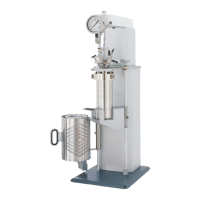
Overview of the manual's content and intended use for Parr Series 4520 Bench Top Reactors.
Crucial safety precautions for operation and maintenance to avoid electrical shock and personal injury.
Details on electrical ratings, voltage, frequency, current, and thermocouple requirements.
Definitions for symbols used in the manual and on the equipment, including caution and earth symbols.
Specifies operating and storage conditions like temperature, humidity, and altitude limits.
Guidelines for safely moving and handling the heavy reactor components.
Instructions for periodic cleaning of exterior surfaces and component maintenance.
Explains the system's design purpose as a high pressure reactor and user's responsibility.
Outlines the user's fundamental duties for safe operation, selection, installation, and maintenance.
Instructions for unpacking, inspecting, and checking all components against the packing list.
Details maximum operating pressure and temperature based on vessel materials and components.
General requirements for workspace, ventilation, and controller positioning.
Notes on connecting cooling and heating assemblies to the controller.
Instructions for securely connecting the motor cord for safety.
Steps for mounting fixed head reactors, including the vessel and heater.
Connecting heater, motor, and thermocouple to the controller.
Connecting leads from accessory packages like tachometers and transducers.
Connecting cooling water to the magnetic drive as per manual 234M.
Connecting tubing to the rupture disc outlet for safe venting.
Connecting the power cord to an appropriate grounded outlet.
Initial check of the stirrer drive system with motor and speed control.
Importance of matching vessel and heater sizes to prevent overheating.
Compares fixed and removable head designs and their operational differences.
Details flat PTFE gasket and self-sealing O-ring closure types.
Identifies the gas release valve and its port location.
Identifies gas inlet valves and their connection to the dip tube.
Identifies the liquid sampling valve and its function with the dip tube.
Identifies the pressure gauge and thermowell components.
Identifies the stirrer shaft assembly and its components.
Identifies adapter bushings and various fittings for valves.
Explains the function and importance of the safety rupture disc.
Details the Type J thermocouple, its installation, and connection.
Describes the pressure gauge, its ranges, and protection methods.
Instructions on using adapters for mounting gauges and valves.
Emphasizes checking gasket/O-ring condition and mating surfaces.
Steps for installing fixed and movable head vessels into the support stand.
Procedures for tightening bolts to seal gaskets and O-rings.
Explains the double valve assembly for gas introduction and sampling.
Instructions for connecting the pressure hose for gas supply.
Steps for safe pressurization and warnings against overfilling.
Procedure for safely withdrawing liquid samples.
How to use the gas release valve for pressure reduction.
Procedures for opening fixed and movable head vessels after a test.
Guidance on performing an initial test with water to check the apparatus.
Information on operating the variable speed electric motor and speed control.
Details on installing and using internal cooling coils.
Information on glass and PTFE liners and their impact on heat transfer.
Describes contents and ordering of spare parts kits.
Information on installing, operating, and maintaining the air motor.
Discusses potential ignition hazards and explosion-proofing considerations.
Options for explosion-proof motors, wiring, and safety barriers.
Hazards and considerations for explosion-proofing controllers and heaters.
Explains factory testing and the importance of regular pressure vessel tests.
Procedures for returning vessels for factory testing and overhaul.
Guidelines for inspecting wiring, connections, and using correct wrenches.
Instructions for installing NPS/NPT fittings, using lubricants, and tape.
Maintenance, cleaning, and troubleshooting procedures for the air motor.
Notes on general cleaning, compression rings, cap screws, and servicing contact.
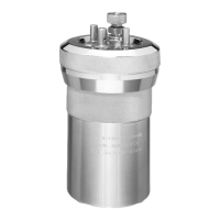
Lists parts for reaction vessels, including cylinders, heads, and internal fittings.
Lists external fittings, adapters, split rings, accessories, and pressure gauges.
Details parts and views specific to removable head configurations.
Details parts and views specific to fixed head configurations.
Lists parts for motors, pulleys, shafts, couplings, and optional tach parts.
Diagram of the overarm assembly with component callouts and RPM table.
Lists parts for serpentine cooling coils, including connectors and nuts.
Diagrams showing cooling coil connections for removable and fixed heads.
Lists part numbers for various vessel heater assemblies.
Diagram of the benchtop stand arrangement with component callouts.
| Model | 4520 |
|---|---|
| Maximum Temperature | 350 °C |
| Stirring Method | Magnetic Drive |
| Material of Construction | Stainless Steel |
| Closure | Split-Ring |
| Heating Method | Electric Heater |