DATASHEET
α
6
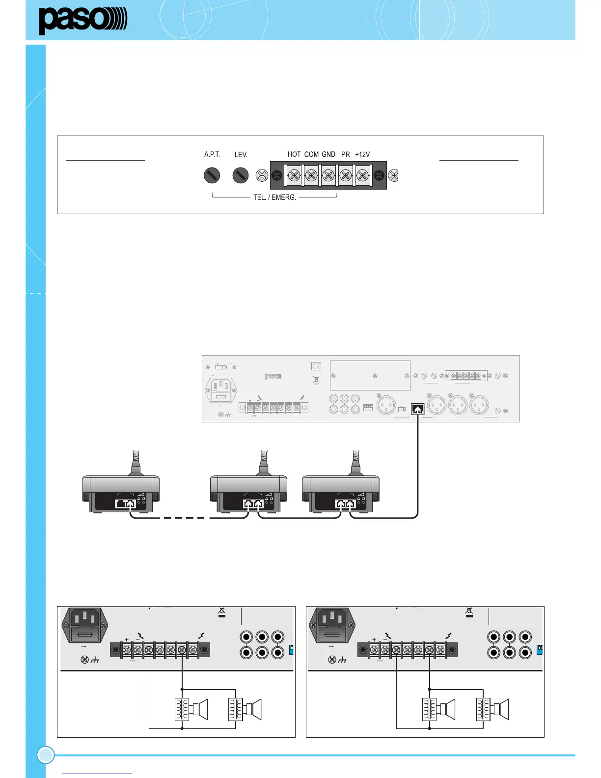
Fig. 3.10.1 Fig. 3.10.2
Fig. 3.7.1
TEL./EMERG.
HOT ingresso (lato caldo)
COM ingresso (lato freddo)
GND massa e schermo
TEL./EMERG.
HOT input (warm side)
COM input (cold side)
GND GND and shield
3.7 Ingresso telefonico
Gli apparecchi sono predisposti per il collegamento ad un sistema telefonico
tramite la morsettiera TEL./EMERG. (22). Tale ingresso è bilanciato a
trasformatore, possiede un proprio controllo di livello - LEV. (23) - ed
è dotato di circuito VOX per la diffusione dei messaggi con priorità più
elevata rispetto a qualsiasi altro ingresso.
3.7 Telephone input
The equipment has provisions for connection to a telephone system
via the TEL./EMERG. terminal strip (22). This input is balanced by a
transformer, has its own level control - LEV. (23) – and is equipped with
a VOX circuit for broadcasting messages with a higher priority than any
other input.
3.8 Precedenza microfonica e segnale di preavviso
Chiudendo i contatti PR e +12V della morsettiera (21) o effettuando una
chiamata dalla postazione B711, viene generato un segnale di preavviso a
due toni (CHIME); è possibile modificare il livello di questo segnale agendo
sul relativo trimmer LEV. (20).
3.8 Microphone precedence and warning signal
When the contacts PR and +12V of the terminal strip (21) are closed, or
when there’s an incoming call from a B711 microphone station, a two-tone
warning signal (CHIME) is generated. It is possible to adjust the level of
the warning signal by means of the LEV. trimmer (20).
3.9 Collegamento delle postazioni
Agli amplificatori della AX3506 e AX3512 possono essere collegate
in modo semplice e veloce le postazioni microfoniche B711/B711-G.
Queste postazioni microfoniche sono caratterizzate entrambe da un
microfono elettrete. Per il collegamento di questi due modelli, è
INDISPENSABILE utilizzare dei cavi STP CAT5.E (schermati).
Fig. 3.9.1
3.9 Connecting the stations
Connecting the B711/B711-G microphone stations to the AX3506 and
AX3512 amplifiers is simple and rapidly achieved.
Both these pre-amplified microphone stations feature electret microphones.
To connect these two models, it is ESSENTIAL to use STP CAT 5.E
cables (shielded).
115V 230V
V 50/60Hz - 400VA
FUSE T2,5A
L
PR +12V
HOT COM
GND
TEL. / EMERG.
LEV.
LEV.
A.P.T.
CHIME
L
CDTAPELINE OUT
AMPLIFIER AX3512
POWER RATING 120 W
CAUTION: DO NOT OBSTRUCT THE OPENING.
REPLACE FUSE WITH SAME TYPE AND VALUE.
DISCONNECT POWER CORD BEFORE OPENING.
100V70V50V8W0V
24V
8A
IN
R
MIC.3UNITS
MIC.2 MIC.1
A.P.T.
PH.
MIC.LINE
MIC.4/LINE
3.10 Uscite di potenza
Le uscite di potenza per i diffusori sono disponibili sulla morsettiera (12).
È possibile realizzare un impianto di diffusione sonora utilizzando sia
diffusori a bassa impedenza (fig. 3.10.1), sia diffusori dotati di traslatore
di linea (fig. 3.10.2).
3.10 Power outputs
The power outputs for the loudspeakers are available on the terminal strip
(12). It is possible to set up a sound-broadcasting system using either
low-impedance loudspeakers (fig. 3.10.1) or loudspeakers equipped with
a line transformer (fig. 3.10.2).
 Loading...