DIGITAL MUSIC AMPLIFIERS
INSTALLATION AND WIRING
PAGE 13
SPECIFICATIONS ARE SUBJECT TO CHANGE WITHOUT NOTICET3015/3030DMA
BALANCED PROGRAM INPUT
The PROGRAM Input is a balanced high level input (1 Volt
Sensitivity) provided specifically for direct connection to a
Satellite Receiver with a balanced Output or other high
level Balanced Program Source. An independent Output
Level Control is provided on the front panel of the Amplifier.
PROGRAM INPUT SENSITIVITY ATTENUATOR
The PROG Input is equipped with a Sensitivity Attenuator
that allows the interface of the PROG Input with Devices
having a wide range of Output Levels.
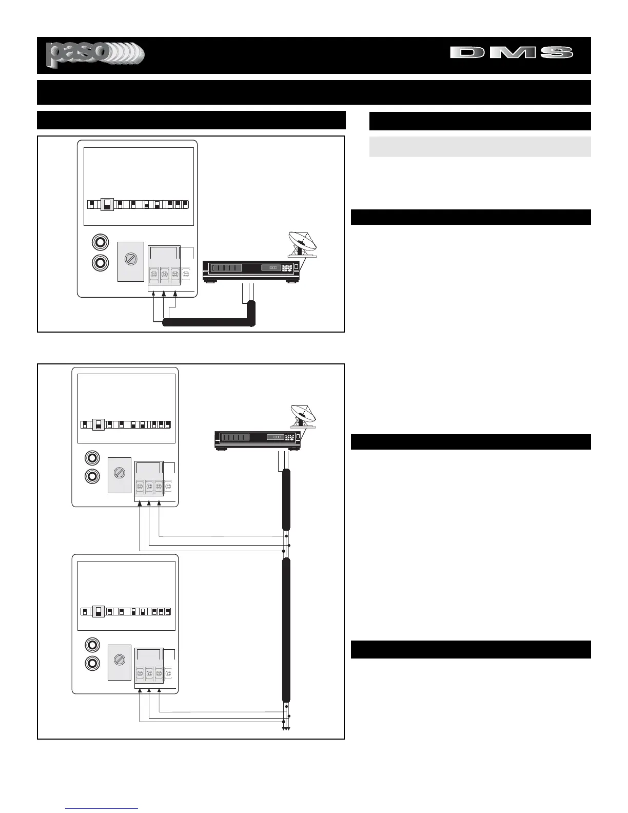
CABLE
To connect the Satellite Receiver to the PROGRAM Input
use a dual conductor shielded audio cable with stripped
wires on both ends. Connect the audio leads to HOT and
COM and the shield to G.
Fig. 13B - BALANCED PROGRAM Input Networking Diagram
NETWORKING
NETWORK APPLICATION
In applications requiring the use of multiple Amplifiers with
a single Satellite Receiver, the Balanced Program Input of
the Amplifier may be used.The Amplifiers are cascaded as
shown in Diagram 13B and then connected to the Satellite
Receiver Balanced Output.
The Music Output Level may be adjusted by using the
PROGRAM Output Level Control available on the front
panel of each Amplifier.
WIRING
To connect the Satellite Receiver to the Amplifiers PRO-
GRAM Input use a dual conductor shielded audio cable
with stripped wires. Connect the audio leads to HOT and
COM and the shield to G.
INPUT 2 (BALANCED PROGRAM)
INPUT 2 SETTING AS A BALANCED PROGRAM INPUT
SET INPUT 2 SWITCH TO PROG
INPUT SWITCH SETTING
CAUTION:
TO PREVENT POSSIBLE DAMAGE TO
SPEAKERS OR THE AMPLIFIER ALL INPUT CONNEC-
TIONS MUST BE MADE WITH THE AMPLIFIER OFF
(POWER OFF).
PROGRAM INPUT MUTING
MUTING - The PROGRAM Input can be Muted or
not when the VOX is activated by Paging from the
MIC Input (1) or the Phone Input when set as TEL.
DIRECT MUTING
If the INPUT 2 MUTE SWITCH is ON, when the
DIRECT MUTING is applied the PROG INPUT is
MUTED (see Muting Functions)
.