UNSWITCHED 117V 500W MAX.
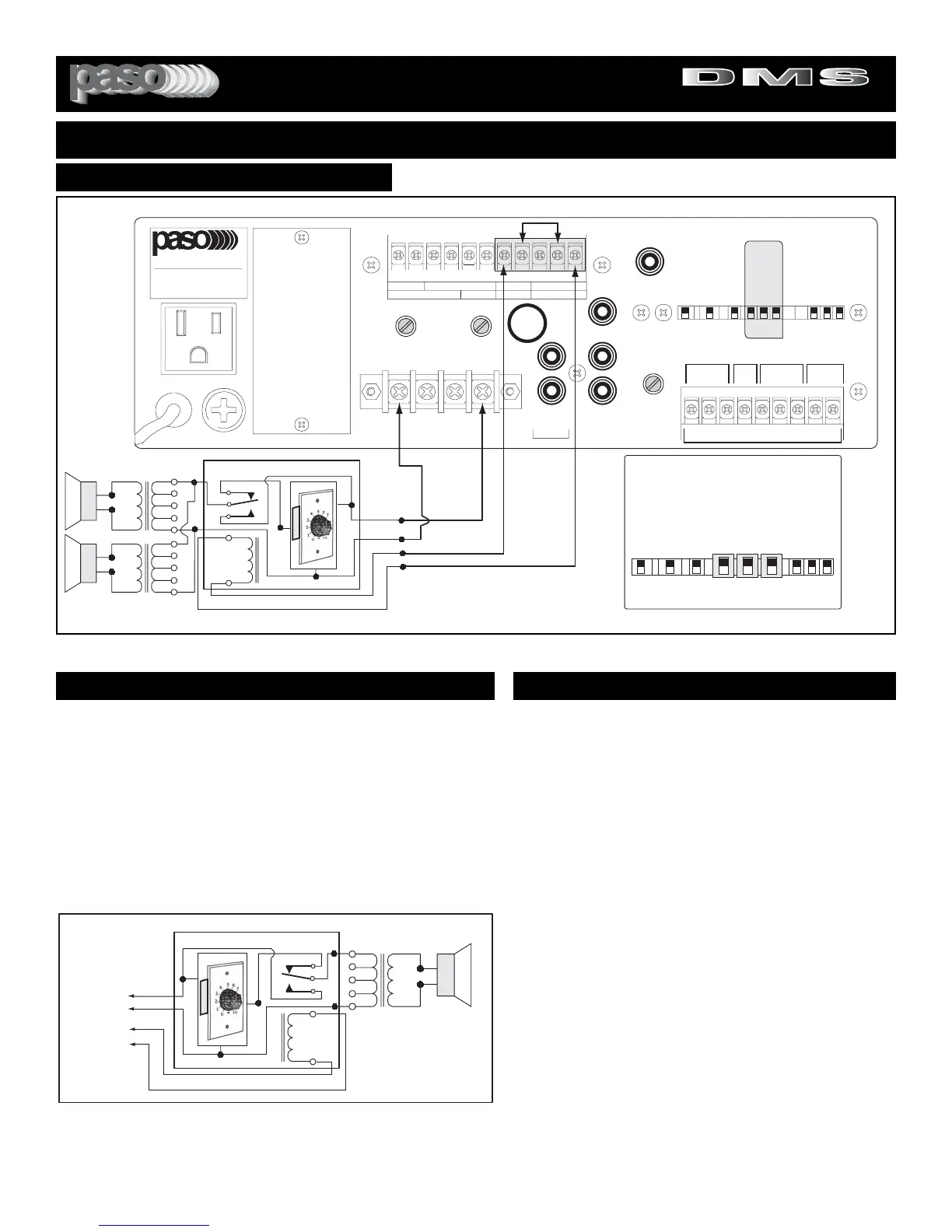
Fig. 24 - Priority Attenuator Connection Diagram
USING PRIORITY ATTENUATORS
AUTOMATIC VOX RELAY
The Amplifier is equipped with a VOX RELAY providing NORMALLY
OPEN and NORMALLY CLOSED Contacts (SPDT SWITCH). Each
time the VOX is activated by Paging from INPUT 1 (set as MIC or TEL)
or by Paging from INPUT 2 (set as MIC) or a PROGRAM from INPUT
2 (set as PROG) the VOX RELAY Terminals C and NO are closed.
24 V DC REGULATED POWER SUPPLY
The Amplifier provides a 24 V - 100 mA DC Output that can be used to
power the Priority Attenuators.Typically the Attenuator will require 24 V
- 10 mA DC Power. Up to 10 Attenuators may be used per installation.
VOX RELAY
PRIORITY ATTENUATORS
In applications requiring that the PAGING Output is at a high-
er Level than the MUSIC PROGRAM Output Level a PRIOR-
ITY ATTENUATOR is required. For this purpose the Amplifier
is equipped with a VOX RELAY and a 24 V DC REGULATED
POWER SUPPLY to operate the Priority Attenuator.
OPERATION
Each time the VOX is activated by Paging from INPUT 1 or
INPUT 2 the VOX RELAY will actuate the PRIORITY ATTEN-
UATOR RELAY and bypass the Attenuator setting. When the
Paging is terminated the VOX turns off the Attenuator Relay
and the Music Level returns to the selected Attenuator setting.
WIRING
1) ATTENUATOR - Connect the COMMON Wire (Black) to
the
0 of the Amplifier Speaker Output and the INPUT Wire
(Red) to the
70 VOLT Terminal. Connect one wire of the
RELAY (White) to the MINUS (-) of the 24 Volt Power Supply
Terminal and the other RELAY Wire (Blue) to the
NO Terminal
of the VOX RELAY on the Amplifier.
2) AMPLIFIER - Bridge Terminals
(+) and C as shown on the
Diagram in Fig. 24.
CABLE REQUIREMENT
Two conductors for the Audio and two conductors for the
Relay. Use AWG18 Wire.