- 9 -
NOTE:
(1)The above electrical wiring diagrams are only for your reference, please subject the heat
pump to the posted wiring diagram.
(2)The heat pump must be earthed well.Earthing the unit is still required to protect you
against short circuits inside the unit.
Disconnect: A disconnector (circuit breaker, fused or un-fused switch) should be located
within sight of and easily accessible from the unit .This is common practice on commercial
and residential heat pumps. It prevents remotely-energizing unattended equipment and
permits turning off power to the unit while the unit is being serviced.
5. Controller’s Operations
LED Display Controller
5.1 Overview
◎ The controller is specially designed for the heat pump, with features as below:
Heating and cooling mode;
Could show and change the running and setting parameters of the system, easy
for user to install and test;
With automatic protection and fault warning function;
With strong system protection function, like compressor delay protection, high
pressure, low pressure, sensor protection,water flow detect, and etc.;
The communication distance between the heat pump unit and wire controller
should be less than 100 meters. The communication port is RS485;
Strong anti-interference, stable performance.
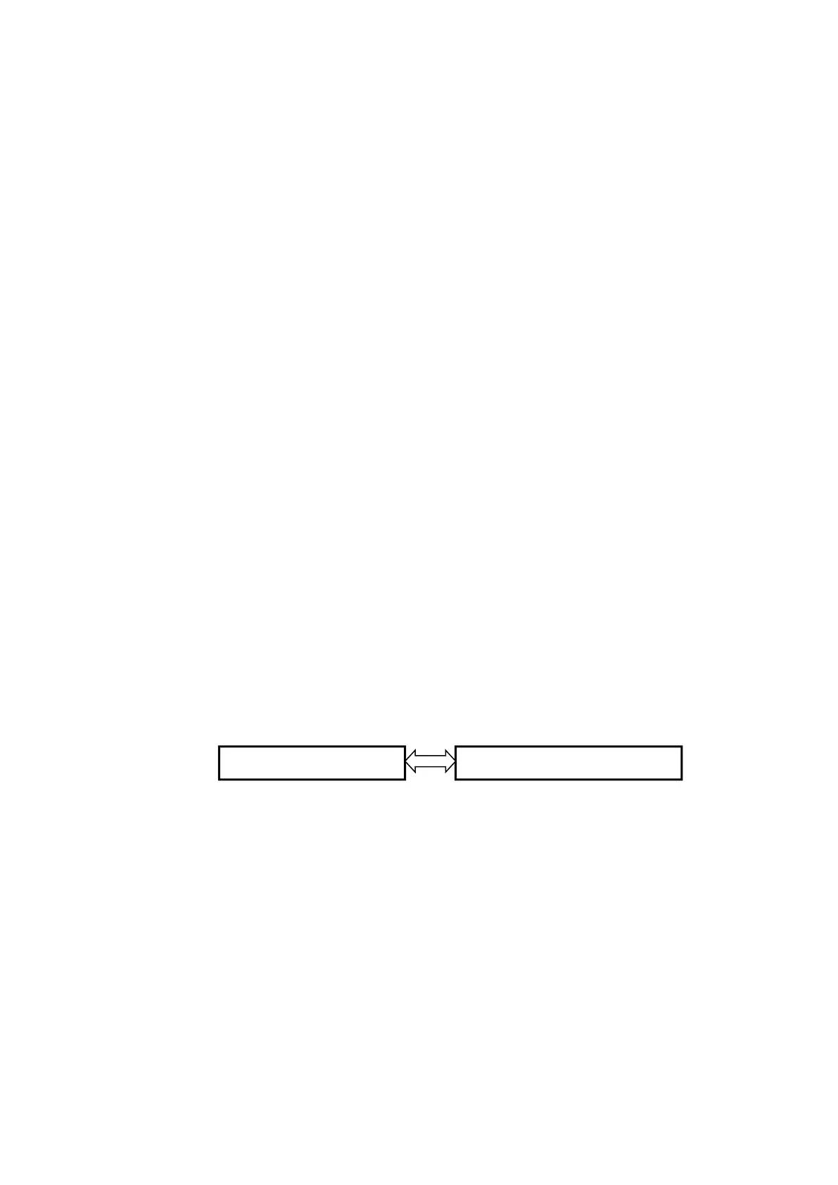
5.2 Basic Model of System Control Chart
◎ Control Principle
The heat pump runs according to the wire controller’s order
The wire controller could change the running parameters and send the running
parameters to the heat pump
The heat pump could detect the running condition and send the information or fault
to the wire controller