8
The electric heater battery with resistance heating element has to be run with a digital flow indicator STR.
The digital flow indicator is either part of the module or has to be installed separately in the supply air duct
with a straight flow distance of 5 x DN.
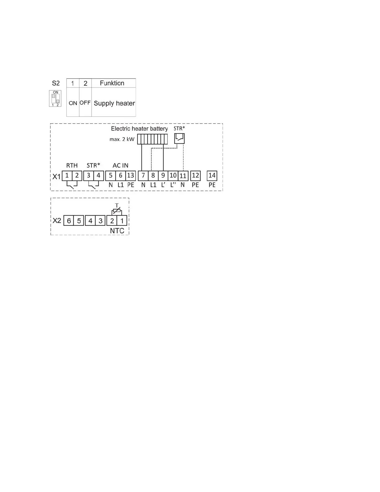
The combination of switch settings of the DIP switch S2, the terminal configuration X1 and X2 for control
of the electric heater battery is shown in figure 7.
Figure 7: Electric heater battery configuration
3.2.2 Water supply heater
The water supply heater has to be installed in the supply air duct of the ventilation unit. The temperature
sensor NTC is installed in the supply air duct downstream the water supply heater. The room
temperature can be controlled by connecting a room thermostat RTH for set-point assignment. This room
thermostat is generally for enabling the supply heater.
If using a water supply heater, a pump is switched on or off via L1. The pump is switched on if RTH is
closed via the room thermostat. The duct temperature, measured by NTC, results of the water
temperature. Therefore, the duct temperature is not controlled via L1.
In addition to the system's frost protection, a frost protection is implemented to protect the water pump. In
case the temperature of the NTC falls below 5°C, the pump is switched off.
Optionally, a proportional valve (motor valve) can be connected to the analog 0-10 V output. The valve
regulates the amount of hot water mixed with the cold water, so the result is the predefined duct
temperature. If the temperature measured rises above the duct temperature, the voltage on the 0-10 V
output is lowered more and more. If the temperature falls below the duct temperature, the voltage is
increased again. The voltage is kept constant within the hysteresis of 1 K around the duct temperature.
The control system has a pi-characteristic and a time constant of 2,5 s. If the temperature measured is,
for example, is 10 k smaller than the duct temperature, the voltage at 0-10 V output is increased from 4 V
to 10 V within 15 s.
The input STR is not evaluated.
The combination of switch settings of the DIP switch S2, the terminal configuration X1 and X2 for control
of the water supply heater is shown in figure 8.