5
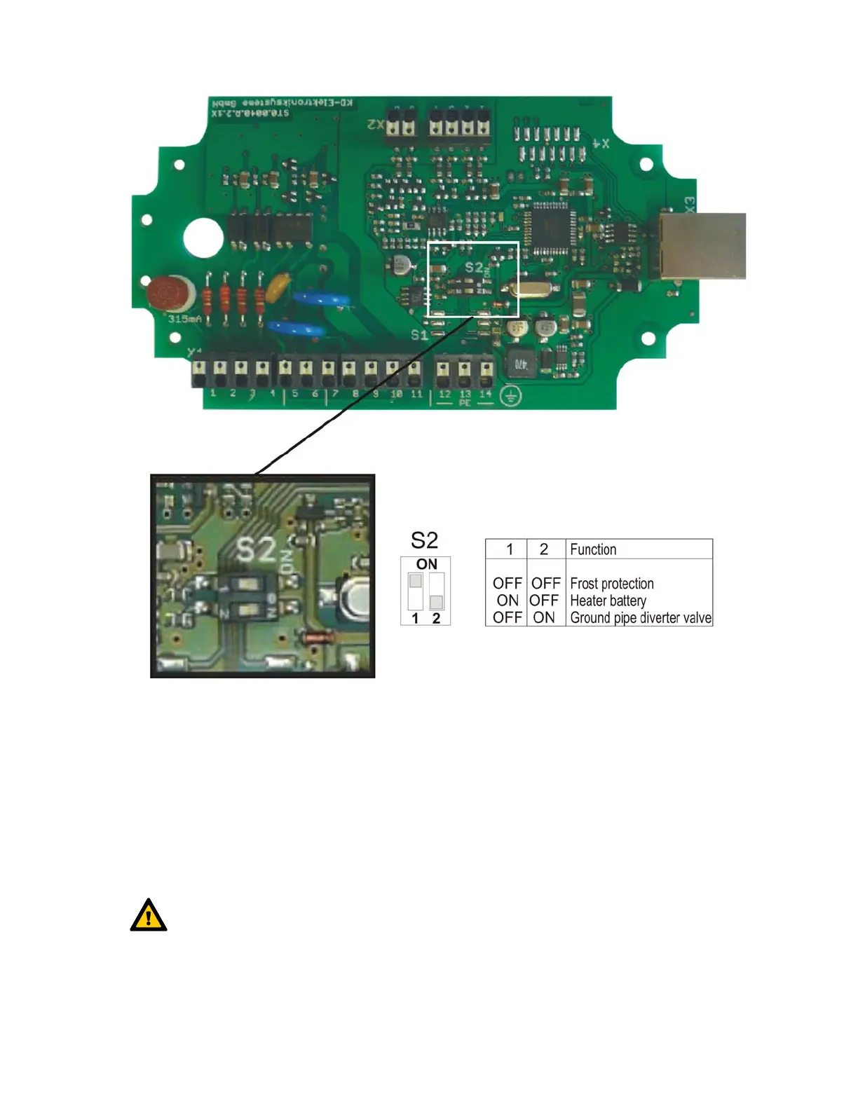
Figure 3: Functions of switch settings S2.1 and S2.2 of the DIP switch S2
3.1 Frost protection operating mode
3.1.1 Electric frost protection heater
The electric frost protection heater has to be integrated in the intake air duct of the ventilation unit. The
temperature sensor NTC has to be installed in the intake air duct downstream the electric frost
protection heater and upstream the intake air connection of the ventilation unit. The electric frost
protection heater heats up the intake air which is led into the heat exchanger, so the temperatures do not
fall below frost protection thresholds and the heat exchanger is able to continue operation without
freezing.
The electric frost protection heater is supplied with pulse packet controlled power via output L1.
Maximum switching capacity 2 kW!
3.1.1.1 Electric frost protection heater with PTC heating element
The electric frost protection heater with PTC heating element does not need a digital flow indicator STR.
The combination of switch settings of the DIP switch S2, the terminal configuration X1 and X2 for control
of the electric frost protection heater with PTC heating element is shown in figure 4.