7
Figure 5: Configuration of electric frost protection heater with resistance heating element
3.1.2 Brine-defroster
The brine-defroster has to be integrated in the intake air duct of the ventilation unit. The temperature
sensor NTC has to be installed in the intake air duct upstream the brine-defroster. A brine-pump is
actuated if a brine-defroster is used. L1 does not issue any pulse packets, but switches the pump on or
off. The temperature conditions are the same as temperature conditions of the electric defroster.
Additionally, a cooling function can be activated for the brine-defroster module (ref. to menu settings/brine
loop cooling). The cooling function cools the air led to the heat exchanger once a predefined temperature
threshold is exceeded.
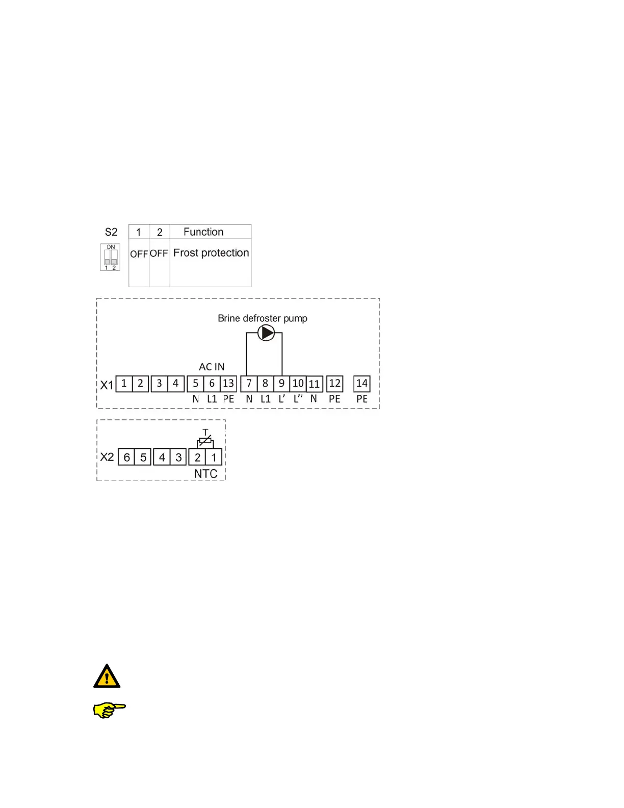
The combination of switch settings of the DIP switch S2, the terminal configuration X1 and X2 for control
of the brine-defroster pump is shown in figure 6.
Figure 6: Brine-defroster configuration
3.2 Supply heater operating mode
3.2.1 Electric heater battery
The electric heater battery has to be installed in the supply air duct of the ventilation unit. The
temperature sensor NTC is installed. The room temperature can be controlled by connecting a room
thermostat RTH for set-point assignment downstream the electric heater battery. This room thermostat
is generally for enabling the supply heater. The pulse packet length control of the electric heater battery is
identical to the pulse packet length control of the electric frost protection heater, except that it is set to a
predefined duct temperature (ref. to menu setup/Post-heating).
Duct temperature control is realized by comparing the actual value of the NTC temperature sensor with
the duct temperature's set-point assignment, the backup duct heater is controlled power modulating
according to the variance.
Maximum switching capacity 2 kW!
The electric heater battery with PTC heating element does not need a digital flow
indicator STR. In this case, a ju,per has to be set between terminal 3 and terminal 4
on terminal strip 1.