- 6 -
Instruction manual
7. ALARM SIGNALLING
Mess. Cause Outputs
“P1” Room probe failure
Compressor output
according to Cy e Cn
“HA” Maximum temperature alarm Outputs unchanged
“LA” Minimum temperature alarm Outputs unchanged
“EA” External alarm Outputs unchanged
“CA” Serious external alarm All outputs OFF
“dA” Door Open
ALARM RECOVERY
Probe alarm “P1” starts some seconds after the fault in the related
probe; it automatically stops some seconds after the probe restarts
normal operation. Check connections before replacing the probe.
Temperature alarms “HA” and “LA” automatically stop as soon as
the temperature returns to normal values.
Alarms “EA” and “CA” (with iF=bA) recover as soon as the digital
input is disabled.
8. TECHNICAL DATA
Housing: self extinguishing ABS
Case: frontal 32x74 mm; depth 50 mm
Mounting: panel mounting in a 71x29 mm panel cut-out
Protection: IP20
Frontal protection: IP65
Connections: disconnectable terminal block ≤ 2,5 mm
2
wiring
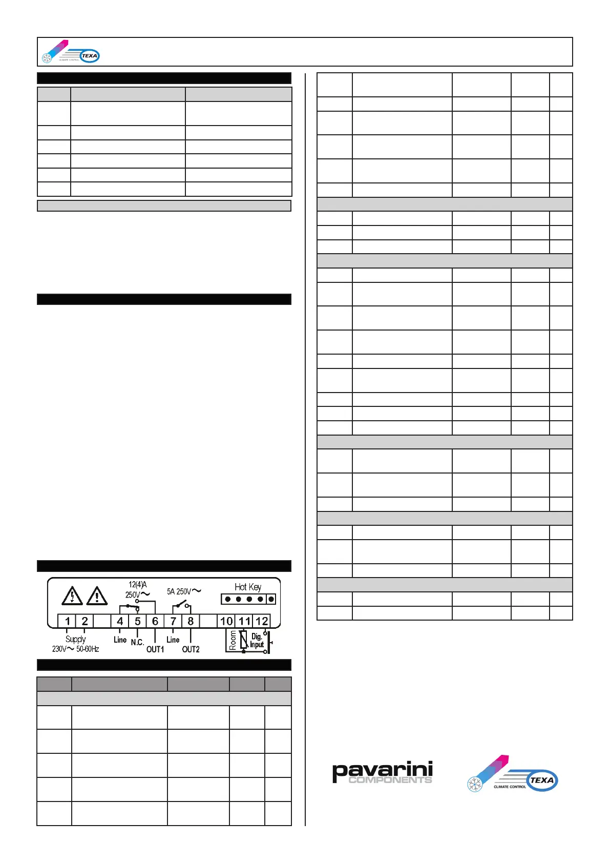
Power supply: 230 Vac ±10%, 50/60 Hz
Power absorption: 3.5 VA max
Display: 2 digits, red LED, 14,2 mm high
Inputs: 1 NTC probe
Digital input: free voltage contact
Relay outputs: Output 1: SPDT 12 A 250 Vac
Output 2: SPST 5 A 250 Vac
Data storing: on the non-volatile memory (EEPROM)
Kind of action: 1B
Pollution grade: 2
Software class: A
Rated impulsive voltage: 2500 V
Overvoltage Category: II
Operating temperature: 0÷60°C
Storage temperature: -25÷60°C
Relative humidity: 20÷85% (no condensing)
Measuring and regulation range: NTC probe: -40÷110°C
Resolution: 0,1°C or 1°C or 1°F (selectable)
Accuracy (ambient temp. 25°C): ±0,1°C ±1 digit
9. WIRING DIAGRAM
10. DEFAULT SETTING VALUES
LABEL DESCRIPTION RANGE DEF. LEV.
REGULATION
- Set point LS ÷ US
35°C
(95°F)
-
Hy Differential
0.1 ÷ 25°C
(1 ÷ 45°F)
2.0°C
(4.0°F)
L1
LS Minimum Set Point
-55°C ÷ SET
(-67°F ÷ SET)
20°C
(68°F)
L2
US Maximum Set Point
SET ÷ 99°C
(SET ÷ 99°F)
50°C
(99°F)
L2
ot First probe calibration
-9.9 ÷ 9.9°C
(-17 ÷ 17°F)
0.0
(0.0)
L2
od
Outputs activation delay
at start up
0 ÷ 99 min 0 L2
AC Anti-short cycle delay 0 ÷ 50 min 4 L2
Lt
Minimum time
compressor ON
0 ÷ 99 s 90 L2
Cy
Compressor ON time
faulty probe
0 ÷ 99 min 1 L2
Cn
Compressor OFF time
faulty probe
0 ÷ 99 min 0 L2
CH Kind of Action CL - Ht CL L1
DISPLAY
CF Measurement units °C - °F °C L1
rE Resolution (only for °C) dE - in dE L1
dy Display delay 0 ÷ 15 min 0 L2
ALARMS
AA Alarm conguration rE - Ab rE L1
AU
Maximum temperature
alarm
AL ÷ 99°C
(AL ÷ 99°F)
10°C
(18°F)
L1
AL
Minimum temperature
alarm
-55°C ÷ AU
(-67°F ÷ AU)
10°C
(18°F)
L1
AH Alarm differential
0.1°C÷25.5°C
(1°F ÷ 45°F)
1.0°C
(2.0°F)
L1
Ad Temperature alarm delay 0 ÷ 99 min 0 L1
dA
Exclusion of temperature
alarm at startup
0 ÷ 99 min 60 L2
At Alarm showing mode AU - rS rS L1
rA Alarm relay mode AU - rS rS L1
tb Alarm relay silencing n - y n L1
OUTPUTS CONFIGURATION
o0 Output 1 conguration
nU / CP / Fn /
AL / AU / db
CP L2
o1 Output 2 conguration
nU / CP / Fn /
AL / AU / db
AL L1
AP Alarm relay polarity CL - OP OP L1
DIGITAL INPUT
iP Digital input polarity CL - OP OP L1
iF
Digital input congura-
tion
EA / bA / do /
Sb / AU / HC
bA L1
di Digital input delay 0 ÷ 99 min 0 L1
OTHER
Pt Parameter code table Read only - - - L2
rL Firmware release Read only - - - L2
/
STRADA CA’ BRUCIATA n°5
46020 PEGOGNAGA – MN – ITALY
TEL. +39(0)376-554511
FAX +39(0)376-550576
www.pavarinicomponents.com
 Loading...